

Полная версия
Optical Engineering Science
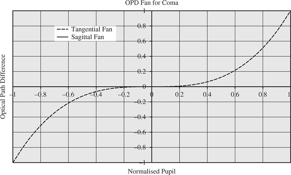
Figure 3.12 OPD fan for coma.
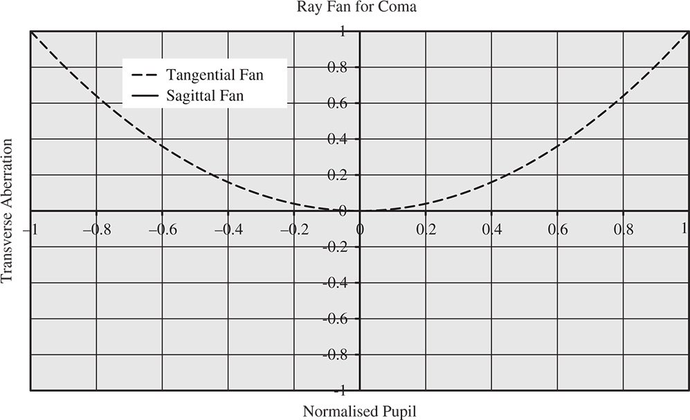
Figure 3.13 Ray fan for coma.
Since the (vector) transverse aberration for coma is non-symmetric, the blur spot relating to coma has a distinct pattern. The blur spot is produced by filling the entrance pupil with an even distribution of rays and plotting their transverse aberration at the paraxial focus. If we imagine the pupil to be composed of a series of concentric rings from the centre to the periphery, these will produce a series of overlapping rings that are displaced in the y direction.
Figure 3.14 shows the characteristic geometrical point spread function associated with coma, clearly illustrating the overlapping circles corresponding to successive pupil rings. These overlapping rings produce a characteristic comet tail appearance from which the aberration derives its name. The overlapping circles produce two asymptotes, with a characteristic angle of 60°, as shown in Figure 3.14.
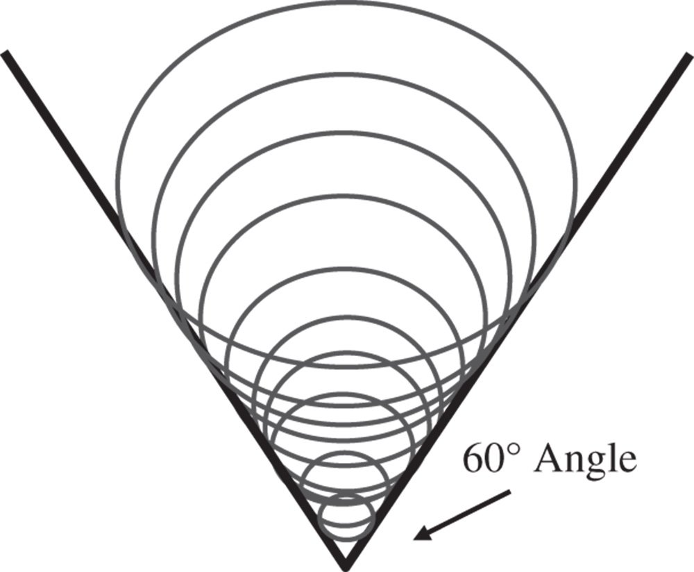
Figure 3.14 Geometrical spot for coma.
To see how these overlapping circles are formed, we introduce an additional angle, the ray fan angle, φ, which describes the angle that the plane of the ray fan makes with respect to the y axis. For the tangential ray fan, this angle is zero. For the sagittal ray fan, this angle is 90°. We can now describe the individual components of the pupil function, px and py in terms of the magnitude of the pupil function, p, and the ray fan angle, φ:

From (3.25) we can express the transverse aberration components in terms of p and φ. This gives:

A is a constant
It is clear from Eq. (3.27) that the pattern produced is a series of overlapping circles of radius A√2p2 offset in y by 2Ap2. Coma is not an aberration that can be ameliorated or balanced by defocus. When analysing transverse aberration, the impact of defocus is to produce an odd (anti-symmetrical) additional contribution with respect to pupil function. The transverse aberration produced by coma, is, of course, even with respect to pupil function, as shown in Figure 3.12. Therefore, any deviation from the paraxial focus will only increase the overall aberration.
Another important consideration with coma is the location of the geometrical spot centroid. This represents the mean ray position at the paraxial focus for an evenly illuminated entrance pupil taken with respect to the chief ray intersection. The centroid locations in x and y, Cx, and Cy, may be defined as follows.
By symmetry considerations, the coma centroid is not displaced in x, but it is displaced in y. Integrating over the whole of the pupil function, p (from 0 to 1) and allowing for a weighting proportional to p (the area of each ring), the centroid location in y, Cy may be derived from Eq. (3.27):
(the term cos2φ is ignored as its average is zero)
So, coma produces a spot centroid that is displaced in proportion to the field angle. The constant A is, of course, proportional to the field angle.
3.5.4 Field Curvature
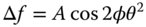
The third Gauss-Seidel term produced is known as field curvature. The OPD associated with field curvature is second order in both field angle and pupil function. Furthermore, there is no dependence upon ray fan angle, as the WFE is circularly symmetric. Unlike in the case for coma, behaviour is identical for the tangential and sagittal ray fans.
From Eq. (3.30), in the case of a single field point, the effect of a quadratic dependence of WFE on pupil function is to produce a uniform defocus. That is to say, a uniform defocus produces a characteristic quadratic pupil dependence in the WFE. The extent of this defocus is proportional to the square of the field angle, producing a curved surface which intersects the paraxial focal plane at zero field angle – the optical axis. If this field curvature were the only aberration, then this curved surface would produce a perfectly sharp image for all these field points. That is to say, with the presence of field curvature, the ideal focal surface is a curved surface or sphere rather than a plane. This is illustrated in Figure 3.15.
Figure 3.15 shows both the tangential and sagittal focal surfaces (S and T), with the optimum focal surface lying between the two. Ideally, for field curvature, the imaging surface should be curved, following the ideal focal surface. If, for instance, only a plane imaging surface is available, then this need not be located at the paraxial focus. This surface can, in principle, be located at an offset, such that the rms WFE is minimised across all fields. In calculating the rms WFE, this would be weighted according to area across all object space, as represented by a circle centred on the optical axis whose radius is the maximum object height.
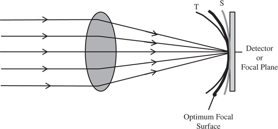
Figure 3.15 Field curvature.
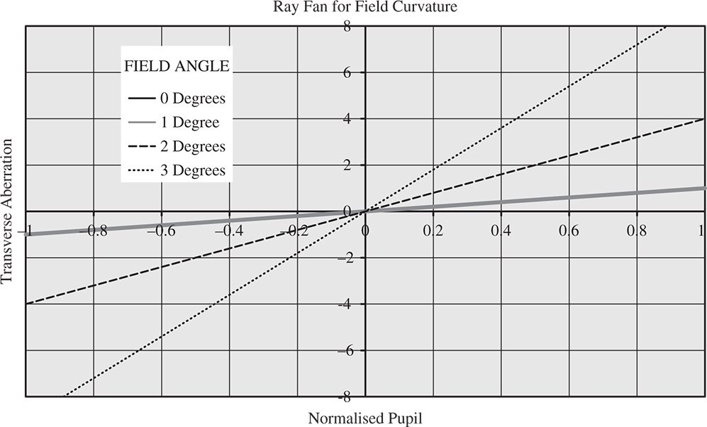
Figure 3.16 Ray fan plots illustrating field curvature.
Clearly, the OPD fan for field curvature is a series of parabolic curves whose height is proportional to the square of the field angle. There is no distinction between the sagittal and tangential fans. Similarly, the ray fans show a series of linear plots whose magnitude is also proportional to the square of the field angle. A series of ray fan plots for field curvature is shown in Figure 3.16.
In view of the symmetry associated with field curvature, the geometrical spot consists of a uniform blur spot whose size increases in proportion to the square of the field angle. In addition, this spot is centred on the chief ray; unlike in the case for coma, there is no centroid shift with respect to the chief ray.
3.5.5 Astigmatism
The fourth Gauss-Seidel term produced is known as astigmatism, literally meaning ‘without a spot’. Like field curvature, the WFE associated with astigmatism is second order in both field angle and pupil function. It differs from field curvature in that the WFE is non-symmetric and depends upon the ray fan angle as well as the magnitude of the pupil function. That is to say, the behaviour of the tangential and sagittal ray fans is markedly different.

In some respects, the OPD behaviour is similar to field curvature, in that, for a given ray fan, the quadratic dependence upon pupil function implies a uniform defocus. However, the degree of defocus is proportional to cos2φ. Thus, the defocus for the tangential ray fan (cos2φ = 1) and the sagittal ray fan (cos2φ = −1) are equal and opposite. Clearly, the tangential and sagittal foci are separate and displaced and this displacement is proportional to the square of the field angle. The displacement of the ray fan focus is set out in Eq. (3.32):
A is a constant
As suggested previously, for a given field angle, the OPD fan would be represented by a series of quadratic curves whose magnitude varies with the ray fan angle. Similarly, the ray fan itself is represented by a series of linear plots whose magnitude is dependent upon the ray fan angle. This is shown in Figure 3.17, which shows the ray fan for a given field angle for both the tangential and sagittal ray fans.
For a general ray, it is possible to calculate the two components of the transverse aberration as a function of the pupil co-ordinates.
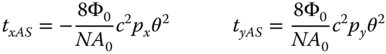
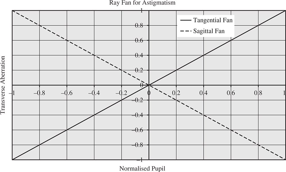
Figure 3.17 Ray fan for astigmatism showing tangential and sagittal fans.
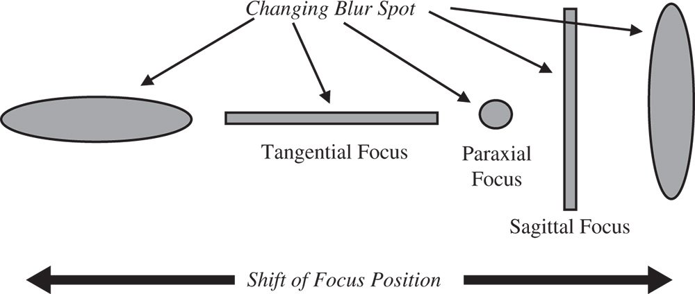
Figure 3.18 Geometric spot vs. defocus for astigmatism.
According to Eq. (3.33), the blur spot produced by astigmatism (at the paraxial focus) is simply a uniform circular disc. Each point in the uniform pupil function simply maps onto a similar point on the blur spot, but with its x value reversed. However, when a uniform defocus is added, similar linear terms (in p) will be added to both tx and ty, having both the same magnitude and sign. As a consequence, the relative magnitude of tx and ty will change producing a uniform elliptical pattern. Indeed, as mentioned earlier, there are distinct and separate tangential and sagittal foci. At these points, the blur spot is effectively transformed into a line, with the focus along one axis being perfect and the other axis in defocus. This is shown in Figure 3.18.
Due to the even (second order) dependence of OPD upon pupil function, there is no centroid shift evident for astigmatism. For Gauss-Seidel astigmatism, its magnitude is proportional to the square of the field angle. Thus, for an on-axis ray bundle (zero field angle) there can be no astigmatism. This Gauss-Seidel analysis, however, assumes all optical surfaces are circularly symmetric with respect to the optical axis. In the important case of the human eye, the validity of this assumption is broken by the fact that the shape of the human eye, and in particular the cornea, is not circularly symmetrical. The slight cylindrical asymmetry present in all real human eyes produces a small amount of astigmatism, even at zero field angle. That is to say, even for on-axis ray bundles, the tangential and sagittal foci are different for the human eye. For this reason, spectacle lenses for vision correction are generally required to compensate for astigmatism as well as defocus (i.e. short-sightedness or long-sightedness).
3.5.6 Distortion
The fifth and final Gauss-Seidel aberration term is distortion. The WFE associated with this aberration is third order in field angle, but linear in pupil function. In fact, a linear variation of WFE with pupil function implies a flat, but tilted wavefront surface. Therefore, distortion merely produces a tilted wavefront but without any apparent blurring of the spot. The WFE variation is set out in Eq. (3.34).
Thus, the only effect produced by distortion is a shift (in the y direction) in the geometric spot centroid; this shift is proportional to the cube of the field angle. However, this shift is global across the entire pupil, so the image remains entirely sharp. The shift is radial in direction, in the sense that the centroid shift is in the same plane (tangential) as the field offset. So, the OPD fan for the tangential fan is linear in pupil function and zero for the sagittal fan. The ray fan is zero for both tangential and sagittal fans, emphasising the lack of blurring.
Taken together with the linear (paraxial) magnification produced by a perfect Gaussian imaging system, distortion introduces another cubic term. That is to say, the relationship between the transverse image and object locations is no longer a linear one; magnification varies with field angle. If the height of the object is hob and that of the image is him, then the two quantities are related as follows:
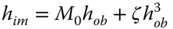
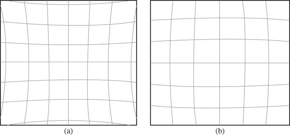
Figure 3.19 (a) Pincushion (positive) distortion. (b) Barrel (negative) distortion.
M0 is the paraxial magnification; ζ is a constant quantifying distortion
If we denote the x and y components of the object and image location by xob, yob and xim, yim respectively, then we obtain:

From Eq. (3.35), it is clear that an object represented by straight line that is offset from the optical axis in object space will be presented as a parabolic line in image space. As such, the image is clearly distorted. The sense and character of the distortion is governed by the sign and magnitude of ζ. This is shown in Figures 3.19a,b.
Where ζ and the distortion is positive, the distortion is referred to as pincushion distortion, as suggested by the form shown in Figure 3.19a. On the other hand, if ζ is negative, the resultant image is distended in a form suggested by Figure 3.19b; this is referred to as barrel distortion.
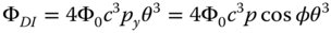
Worked Example 3.1 The distortion of an optical system is given as a WFE by the expression, 4Φ0c3pcosφθ3, where Φ0 is equal to 50 μm and c = 1. The radius of the pupil, r0, is 10 mm. What is the distortion, expressed as a deviation in percent from the paraxial angle, at a field angle of 15°? From Eq. (3.12) and when expressed as an angle, the transverse aberration generated is given by:
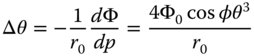
The cosφ term expresses the fact that the direction of the transverse aberration is in the same plane as that of the object/axis. The proportional distortion is therefore given by:
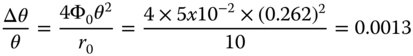
(dimensions in mm; angles in radians)
The proportional distortion is therefore 0.13%.
3.6 Summary of Third Order Aberrations
At this stage it will be useful to summarise the five Gauss-Seidel aberrations in terms of the pupil and field dependence of their OPD and ray fans. It should be noted that for all Gauss-Seidel aberrations, the order of the pupil dependence and the order of the field angle dependence sum to four (for the OPD). In particular, it is important for the reader to understand how the different types of aberration vary with both pupil size and field angle. For example, in many optical systems, such as telescopes and microscopes, the range of field angles tend to be significantly smaller than the larger angles subtended to the pupil. Therefore, for such instruments, those aberrations with a higher-order pupil dependence, such as spherical aberration (4) and coma (3), will predominate.
3.6.1 OPD Dependence
The list below sets out the WFE dependence of the five Gauss-Seidel aberrations on pupil function, p, and field angle, θ.
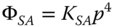
● Spherical Aberration: ΦSA ∝ p4
● Coma: ΦCO ∝ p3θ
● Field Curvature: ΦFC ∝ p2θ2
● Astigmatism: ΦAS ∝ p2θ2
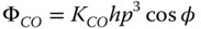
● Distortion: ΦDI ∝ pθ3
To quantify each aberration, we can define a coefficient, K, which describes the magnitude (in units of length) of the aberration. In addition, as well as normalising the pupil function, we can also normalise the field angle by introducing the quantity, h, which represents the ratio, θ/θ0, the ratio of the field angle to the maximum field angle.
The reader should take particular note of the form of Eq. (3.40). The description of astigmatism here is such that the mean defocus over all orientations of the ray fan is taken to be zero. However, other representations adopt the convention that the defocus is zero for the sagittal ray and the balance of the astigmatism is incorporated into the field curvature. That is to say, in these conventions, the astigmatism is taken to be proportional to cos2φ, rather than cos2φ, as in Eq. (3.40). Of course, in using cos2φ, an average defocus of the same form as field curvature is introduced, hence the reason for adopting the convention used here. If the field curvature and astigmatism were redefined according to that convention, then the following revised description would apply:
3.6.2 Transverse Aberration Dependence
The ray fan or transverse aberration dependence upon pupil function and field angle is such that the order of the two variables sum to three, as opposed to four for OPD. The dependence of transverse aberration is listed below:
● Spherical Aberration: tSA ∝ p3
● Coma: tCO ∝ p2θ
● Field Curvature: tFC ∝ pθ2
● Astigmatism: tAS ∝ pθ2
● Distortion: ΦAS ∝ θ3
3.6.3 General Representation of Aberration and Seidel Coefficients
The analysis presented in this chapter has demonstrated the power of using the OPD as a way of describing aberrations. More generally, when expressed as a WFE, it can be used to describe the deviation of a specific wavefront from an ideal wavefront that converges on a specific reference point. As such, this deviation can be used to describe defocus, which shows a quadratic dependence on pupil function and tilt, where the WFE is plane surface that is tilted about the x or y axis (the optical axis being the z axis). The standard representation for describing and quantifying generic WFE and aberration behaviour is shown in Eq. (3.44).
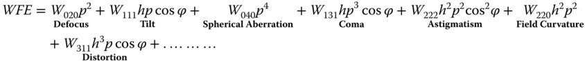
p is the pupil function and h is the object height (proportional to field angle θ); φ is the ray fan angle.
In the general term, Wabc, ‘a’ describes the order of the object height (field angle dependence), ‘b’ describes the order of the pupil function dependence and ‘c’ describes the dependence on the ray fan angle. The defocus and tilt, are of course paraxial terms. Overall, the dependence of each coefficient is given by Eq. (3.45):
It should be noted that this convention incorporates powers of cosφ, so the astigmatism term contains some average field curvature. Describing each of the aberration coefficients introduced earlier in terms of these coefficients gives the following:


Another convention exists of which the reader should be aware. These are the so called Seidel coefficients, named after the nineteenth century mathematician, Phillip Ludwig von Seidel, who first elucidated the five monochromatic aberrations. The coefficients are usually denominated, SI, SII, SIII, SIV, and SV, referring to spherical aberration, coma, astigmatism, field curvature, and distortion. They nominally quantify the WFE, as the other coefficients do, but their magnitude is determined by the size of the blur spot that the aberration creates. The correspondence of these terms is as follows:


The form of Eq. (3.54) is interesting. When compared to the definition of W220 in Eq. (3.48), an additional amount of astigmatism has been compounded with the field curvature. As such, this new representation of field curvature, SIV represents a fundamental and important property of an aberrated optical system and is referred to as the Petzval curvature. Its significance will be discussed more fully in the next chapter.
The treatment of aberrations, thus far, has been entirely generic. We have introduced the five Gauss-Seidel aberrations without specific reference to how they are generated at specific optical surfaces and by individual optical components. This will be discussed in detail in the next chapter. The most important feature of this treatment is that the third order aberrations are additive through a system when described in terms of OPD. That is to say, the five aberrations may be calculated independently at each optical surface and summed over the entire optical system. This analysis is an extremely powerful tool for characterisation of aberration in a complex system.
Further Reading
Born, M. and Wolf, E. (1999). Principles of Optics, 7e. Cambridge: Cambridge University Press. ISBN: 0-521-642221.
Hecht, E. (2017). Optics, 5e. Harlow: Pearson Education. ISBN: 978-0-1339-7722-6.
Kidger, M.J. (2001). Fundamental Optical Design. Bellingham: SPIE. ISBN: 0-81943915-0.
Kidger, M.J. (2004). Intermediate Optical Design. Bellingham: SPIE. ISBN: 978-0-8194-5217-7.
Longhurst, R.S. (1973). Geometrical and Physical Optics, 3e. London: Longmans. ISBN: 0-582-44099-8.
Mahajan, V.N. (1991). Aberration Theory Made Simple. Bellingham: SPIE. ISBN: 0-819-40536-1.
Mahajan, V.N. (1998). Optical Imaging and Aberrations: Part I. Ray Geometrical Optics. Bellingham: SPIE. ISBN: 0-8194-2515-X.
Mahajan, V.N. (2001). Optical Imaging and Aberrations: Part II. Wave Diffraction Optics. Bellingham: SPIE. ISBN: 0-8194-4135-X.
Slyusarev, G.G. (1984). Aberration and Optical Design Theory. Boca Raton: CRC Press. ISBN: 978-0852743577.
Smith, F.G. and Thompson, J.H. (1989). Optics, 2e. New York: Wiley. ISBN: 0-471-91538-1.
4
Aberration Theory and Chromatic Aberration
4.1 General Points
In the previous chapter, we developed a generalised description of third order aberration, introducing the five Gauss-Seidel aberrations. The motivation for this is to give the reader a fundamental understanding and a feel for the underlying principles. At the same time, it is fully appreciated that optical system design and detailed analysis of aberrations is underpinned by powerful optical software tools. Nevertheless, a grasp of the underlying principles, including an appreciation of the form of ray fans and optical path difference (OPD) fans, greatly facilitates the application of these sophisticated tools.
The treatment presented here is restricted to consideration of third order aberrations. Before the advent of powerful software analysis tools, the designer was compelled to resort to a much more elaborate and complex analysis, in particular introducing an analytical treatment of higher order aberrations. For all the labour that this would involve, the reader would gain little in terms of a useful understanding that could be applied to current design tools. As the third order aberrations are third order in transverse aberration and fourth order in OPD, so succeeding higher order aberrations are fifth, seventh etc. order in transverse aberration, but sixth, eighth order in OPD. That is to say, aberrations, whose order is expressed conventionally in terms of the transverse aberration, can only be odd. One can re-iterate the analysis of Section 3.4 to generate the form and number of terms involved in the higher order aberrations. This is left to the reader, but it is straightforward to derive the number of distinct terms Nn as a function of aberration order, n: