

 полная версия
Handwork in Wood
There is diversity of practice in the distribution of tools on the general case and on the individual benches. Some tools, like the plane and chisel, and try-square, are so frequently in use that each worker must have one at hand. As to others, the demand must determine the supply. One other consideration may be expressed by the principle that those tools, the use of which is to be encouraged, should be kept as accessible as possible, and those whose use is to be discouraged, should be kept remote. Some tools, like files, it may be well to keep in a separate locker to be had only when asked for.
A cabinet of drawers, such as that shown in Fig. 240, for holding nails, screws, and other fastenings, is both a convenience and a material aid in preserving the order of the shop.
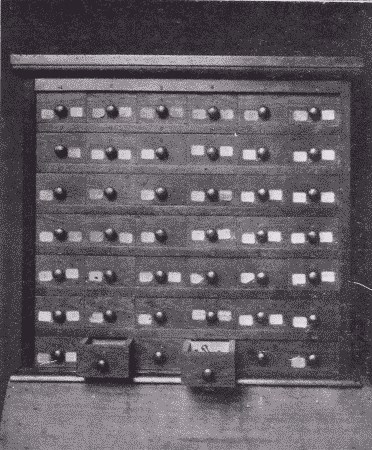
Fig. 240. Nail and Screw Cabinet.
As for the care of tools during vacation, they should be smeared with vaseline, which is cheap, and put away out of the dampness. The planes should be taken apart and each part smeared. To clean them again for use, then becomes an easy matter. The best method of removing rust and tarnish is to polish the tools on a power buffing wheel on which has been rubbed some tripoli. They may then be polished on a clean buffer without tripoli.
The Lockers. In order to maintain good order in the shop, an almost indispensable part of the equipment is a set of lockers for holding the unfinished work of pupils. An inexpensive outfit may consist simply of sets of shelves, say 5" apart, 12" deep, and 18" long, Fig. 241. Ordinary spring-roller curtains may be hung in front of each set of shelves to conceal and protect the contents. Such a case should cost at the rate of about 40c. for each compartment. A more substantial and more convenient case, shown in Fig. 242, consists of compartments each 9½" high, 6" wide, and 18" deep. These proportions may be changed to suit varying conditions. In front of each tier of 12 compartments is a flap door opening downward. Such a case built of yellow pine (paneled) may cost at the rate of $1.00 per compartment.
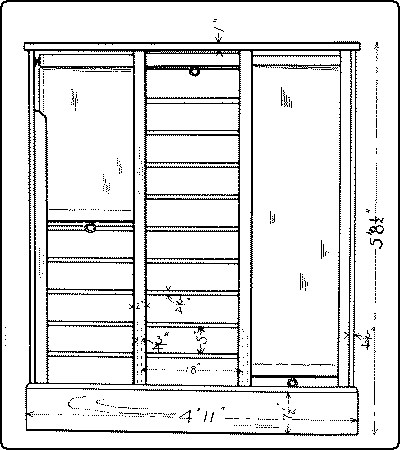
Fig. 241. An Inexpensive Locker for Unfinished Work.
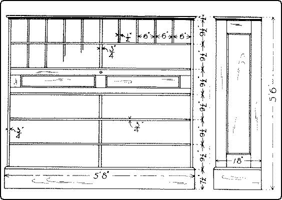
Fig. 242. A More Expensive Locker for Unfinished Work.
There should, of course, be a separate compartment for each pupil using the shop. Where possible, there should be a special table for staining and gluing. Where strict economy must be practiced, a good sized kitchen table covered with oilcloth answers every purpose. A better equipment would include a well-built bench, such as that shown in Fig. 243, the top and back of which are covered with zinc.
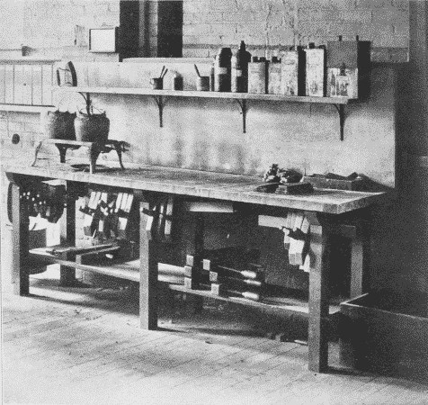
Fig. 243. Gluing and Staining Bench Covered with Zinc.
Where no staining-table is possible, temporary coverings of oilcloth may be provided to lay over any bench which is convenient for the purpose.
Care of brushes and materials used in finishing wood. Shellac should be kept in glass or pottery or aluminum receptacles but not in any metal like tin, which darkens it. A good plan is to have a bottle for fresh, untouched shellac, a wide-mouthed jar for that which has been diluted and used, and an enameled cup for use. There should also be a special brush, Fig. 244. At the time of using, first see that the brush is soft and pliable. If it is stiff, it can be soaked quickly and softened in a little alcohol in the cup. This alcohol may then be poured into the jar and mixed in by shaking. Then pour out a little from the jar into the cup, and if it is too thin, thicken with some fresh shellac. After using, pour back the residue into the jar, carefully wiping the brush on the edge of the jar; and if it is not to be used again for some time, rinse it in a little alcohol, which may also be poured into the jar, which should then be covered. What little shellac remains in the brush and cup will do no harm and the brush may be left standing in the cup until required. The important things are to keep the shellac cup and brush for shellac only, (indeed, it is a good plan to label them "SHELLAC ONLY,") and to keep the shellac covered so that the alcohol in it will not evaporate. In a pattern-making shop, where the shellac cup is to be frequently used, it is well to have cups with covers thru which the brushes hang, like the brush in a mucilage jar.
Fig. 244. Shellac Utensils.
Varnish brushes need to be cleaned thoroly after each using. If they get dry they become too hard to be cleaned without great difficulty.
Brushes for water stains are easily taken care of by washing with water and then laying them flat in a box. Cups in which the water stains have been used can also be easily rinsed with water.
Brushes for oil stains are most easily kept in good condition, by being hung in a brush-keeper, Fig. 245, (sold by Devoe & Reynolds, 101 Fulton St., N. Y. C.) partly filled with turpentine. The same brushes may also be used for fillers.
Fig. 245. Brush-keeper.
Oil stains should be poured back into their respective bottles, and the cups wiped out with cotton waste. When they get in bad condition, they can be cleaned readily after a preliminary soaking in a strong solution of potash. The same treatment may be given to brushes, but if they are left soaking too long in the solution, the bristles will be eaten off.
EQUIPMENT AND CARE OF THE SHOPReferences16
Murray, Year Book 1906, p. 69.
Bailey, M. T. Mag., 9: 138. Dec. '07.
Robillion, pp. 48-90.
Hammacher and Schlemmer, passim.
CHAPTER VII.
THE COMMON JOINTS
Wherever two or more pieces of wood are fastened together we have what is properly called joinery. In common usage the term indicates the framing of the interior wood finish of buildings and ships, but it is also used to include cabinet-making, which is the art of constructing furniture, and even the trades of the wheelwright, carriage-maker, and cooper. Since joinery involves the constant use of joints, a reference list of them, with illustrations, definitions, uses, and directions for making typical ones may be of convenience to workers in wood.
HEADING JOINTSNo. 1. A lapped and strapped joint is made by laying the end of one timber over another and fastening them both together with bent straps on the ends of which are screws by which they may be tightened. It is a very strong joint and is used where the beams need lengthening as in false work or in long ladders and flag poles.
Fig. 264-1 Lapped and Strapped
No. 2. A fished joint is made by butting the squared ends of two timbers together and placing short pieces of wood or iron, called fish-plates, over the faces of the timbers and bolting or spiking the whole firmly together. It is used for joining timbers in the direction of their length, as in boat construction.
Fig. 264-2 Fished
No 3. In a fished joint keys are often inserted between the fish-plate and beam at right angles to the bolts in order to lessen the strain that comes upon the bolts when the joint is subjected to tension. In wide pieces and for extra strength, as in bridge work, the bolts may be staggered.
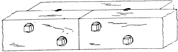
Fig. 264-3 Fished and keyed
Nos. 4, 5, 6 and 7. A scarf or spliced joint is made by joining together with flush surfaces the ends of two timbers in such a way as to enable them to resist compression, as in No. 4; tension, as in No. 5; both, as in No. 6, where the scarf is tabled; or cross strain as in No. 7. No. 4 is used in house sills and in splicing out short posts, Nos. 5 and 6 in open frame work. No. 7 with or without the fish-plate, is used in boats and canoes, and is sometimes called a boat-builder's joint, to distinguish it from No. 4, a carpenter's joint. A joint to resist cross strain is stronger when scarfed in the direction of the strain than across it. No. 7 is the plan, not elevation, of a joint to receive vertical cross strain.
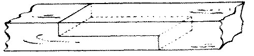
Fig. 264-4 Spliced for compression

Fig. 264-5 Spliced for tension

Fig. 264-6 Spliced and Tabled

Fig. 264-7 Spliced for cross strain
BUTT JOINTS
No. 8. A doweled butt-joint is made by inserting, with glue, dowel-pins into holes bored into the two members. The end of one member is butted against the face or edge of the other. It is used in cabinet-making where the presence of nails would be unseemly.
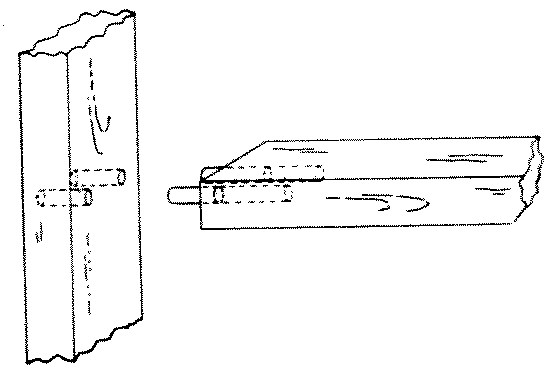
Fig. 264-8 Dowelled butt
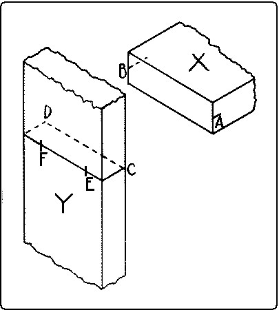
Fig. 246. Lay-out by Thru Dowling.
In a doweled butt-joint the dowels may go clear thru the outside member, and be finished as buttons on the outside, where they show. To lay out this joint mark near the ends of the edges of the abutting member, X, Fig. 246, center-lines A B. Draw on the other member Y, a sharp pencil-line to which when the lines AB on X are fitted, X will be in its proper place. Carry the line around to the other side of Y and locate on it the proper centers for the dowel-holes E and F. Then fasten on the end of X a handscrew in such a way that the jaws will be flush with the end. With another handscrew, clamp this handscrew to Y in such a way that the marks on the two pieces match, A to C and B to D, Fig. 247. Bore at the proper places, E and F, holes directly thru Y into X.
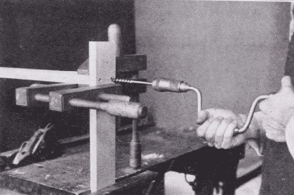
Fig. 247. Thru Boring for a Butt Joint.
Fig. 248 illustrates the gluing together of a four-legged stand in which the joints are made in this way. The cross-lap joints of the stretchers are first glued together, then the other joints are assembled without glue, to see that all the parts fit and finally two opposite sides are glued at a time. Pieces of paper are laid inside the gluing blocks to prevent them from sticking to the legs.
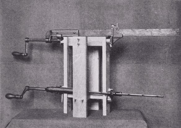
Fig. 248. Gluing-Up a Four-Legged Stand.
In case the dowels are to be hidden the chief difficulty is to locate the holes properly. One method of procedure is as follows: To dowel the end of one member against the face of the other as a stringer into a rail or a rail into a table leg, first lay out the position of the dowels in the end of the first member, X, Fig. 249. Gage a center-line, A B, across this end lengthwise, locate the centers of the dowel-holes, and square across with a knife point, as CD and EF. Gage a line on the other member to correspond with the line AB. On the face so gaged, lay the first member on its side so that one arris lies along this gaged line and prick off the points D and F, to get the centers of the dowel-holes.
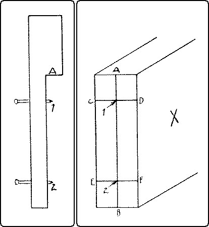
Fig. 249. Laying out a Dowel Joint.
If, as is usual, there are a number of similar joints to be made, a device like that shown in Fig. 249 will expedite matters. 1 and 2 are points of brads driven thru a piece of soft wood, which has been notched out, and are as far apart as the dowels. A-1 is the distance from the working edge of the rail to the first dowel. The same measure can be used from the end of the leg.
When the centers are all marked, bore the holes. Insert the dowels into the holes and make a trial assembly. If any rail is twisted from its proper plane, note carefully where the error is, take apart, glue a dowel into the hole, that is wrong, pare it off flush with the surface, and re-bore in such a place that the parts, when assembled will come up true. When everything fits, glue and clamp together.
No. 9. A toe-nailed joint is made by driving nails diagonally thru the corners of one member into the other. It is used in fastening the studding to the sill in balloon framing.
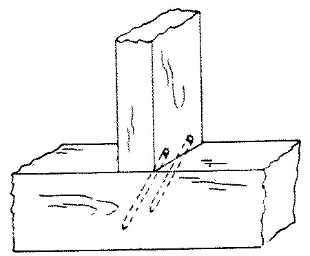
Fig. 264-9 Toe-nailed
No. 10. A draw-bolt joint is made by inserting an iron bolt thru a hole in one member and into the other to meet a nut inserted from the side of the second member. It is very strong and is used in bench construction, wooden machinery, etc.
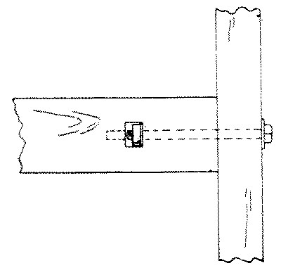
Fig. 264-10 Draw-bolt
No. 11. A plain butt-joint is one in which the members join endwise or edgewise without overlapping. It is used on returns as in ordinary boxes and cases.
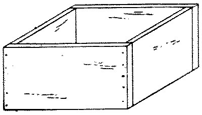
Fig. 264-11 Plain butt
No. 12. A glued and blocked joint is made by gluing and rubbing a block in the inside corner of two pieces which are butted and glued together. It is used in stair-work and cabinet-work, as in the corners of bureaus.
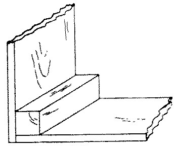
Fig. 264-12 Glued and blocked
No. 13. A hopper-joint is a butt-joint, but is peculiar in that the edges of the boards are not square with their faces on account of the pitch of the sides. It is used in hoppers, bins, chutes, etc. The difficulty in laying out this joint is to obtain the proper angle for the edges of the pieces. This may be done as follows: After the pieces are planed to the correct thickness, plane the upper and lower edges of the end pieces to the correct bevel as shown by the pitch of the sides. Lay out the pitch of the sides of the hopper on the outside of the end pieces. From the ends of these lines, on the upper and lower beveled edges score lines at right angles with the knife and try-square. Connect these lines on what will be the inside of the hopper. Saw off the surplus wood and plane to the lines thus scored. The side pieces may be finished in the same way, and the parts are then ready to be assembled.
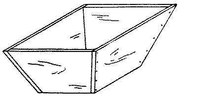
Fig. 264-13 Hopper
HALVING-JOINTS
A halved joint is one in which half the thickness of each member is notched out and the remaining portion of one just fits into the notch in the other, so that the upper and under surfaces of the members are flush.
No. 14. A cross-lap joint is a halved joint in which both members project both ways from the joint. This is a very common joint used in both carpentry and joinery, as where stringers cross each other in the same plane.
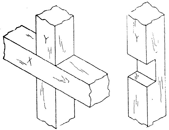
Fig. 264-14 Cross lap
The two pieces are first dressed exactly to the required size, either separately or by the method of making duplicate parts, see Chap. IX, p. 204. Lay one member, called X, across the other in the position which they are to occupy when finished and mark plainly their upper faces, which will be flush when the piece is finished. Locate the middle of the length of the lower piece, called Y, on one arris, and from this point lay off on this arris half the width of the upper piece, X. From this point square across Y with the knife and try-square. Lay X again in its place, exactly along the line just scored. Then mark with the knife on Y the width of X, which may then be removed and the second line squared across Y. From these two lines square across both edges of Y to approximately one-half the thickness. Now turn X face down, lay Y on it, and mark it in the same way as Y. Set the gage at one-half the thickness of the pieces, and gage between the lines on the edges, taking care to hold the head of the gage against the marked faces. Then even if one piece is gaged so as to be cut a little too deep, the other will be gaged so as to be cut proportionately less, and the joint will fit.
Cut a slight triangular groove on the waste side of the knife-marks, Fig. 91, p. 66, saw accurately to the gaged lines, and chisel out the waste as in a dado, see Figs. 70 and 71, p. 56.
The bottom of the dado thus cut should be flat so as to afford surface for gluing. When well made, a cross-lap joint does not need to be pounded together but will fit tight under pressure of the hands.
No. 15. A middle-lap joint or halved tee is made in the same way as a cross-lap joint, but one member projects from the joint in only one direction, it is used to join stretchers to rails as in floor timbers.
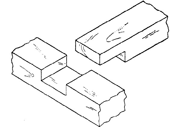
Fig. 265-15 Middle lap
No. 16. An end-lap joint is made in the same way as a cross-lap joint except that the joint is at the end of both members. It is used at the corners of sills and plates, also sometimes in chair-seats.
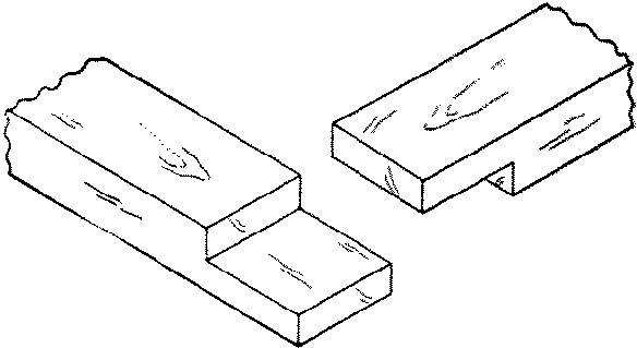
Fig. 265-16 End lap
To make an end-lap joint, place the members in their relative positions, faces up, and mark plainly. Mark carefully on each member the inside corner, allowing the end of each member slightly (1⁄16") to overlap the other. Square across at these points with a sharp knife point, on the under side of the upper member, and on the upper side of the lower member. Now proceed as in the cross-lap joint, except that the gaged line runs around the end and the cutting must be done exactly to this line.
No. 17. In an end-lap joint on rabbeted pieces the joint must be adapted to the rabbet. The rabbet should therefore be plowed before the joint is made. The rabbet at the end of the piece X is cut not the entire width of the piece Y, but only the width of the lap,—c-f = a-e. This joint is used occasionally in picture-frames.
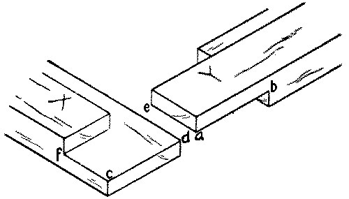
Fig. 265-17 End lap with rabbet
No. 18. A dovetail halving or lap-dovetail is a middle-lap joint with the pin made dovetail in shape, and is thus better able to resist tension. It is used for strong tee joints.
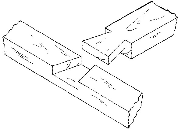
Fig. 265-18 Dovetail halving
No. 19. A beveled halving is made like a middle-lap joint except that the inner end of the upper member is thinner so that the adjoining cheeks are beveled. It is very strong when loaded above. It was formerly used in house framing.
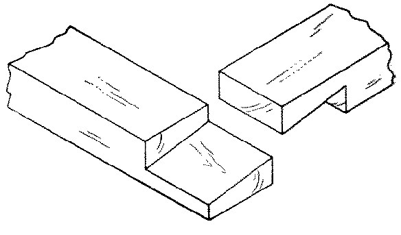
Fig. 265-19 Beveled halving
MODIFIED HALVING JOINTS
No. 20. A notched joint is made by cutting out a portion of one timber. It is used where it is desired to reduce the height occupied by the upper timber. Joists are notched on to wall plates.
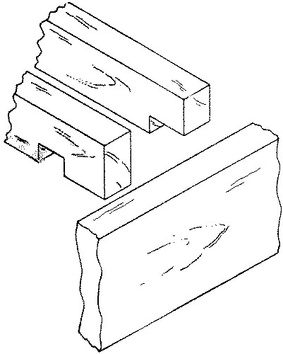
Fig. 265-20 Notched
No. 21. A checked joint or double notch is made by cutting out notches from both the timbers so as to engage each other. It is used where a single notch would weaken one member too much.
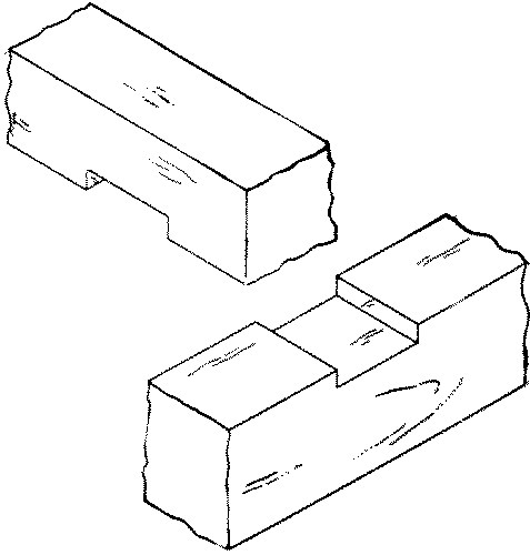
Fig. 265-21 Checked
No. 22. A cogged or corked or caulked joint is made by cutting out only parts of the notch on the lower piece, leaving a "cog" uncut. From the upper piece a notch is cut only wide enough to receive the cog. A cogged joint is stronger than a notched because the upper beam is not weakened at its point of support. It is used in heavy framing.
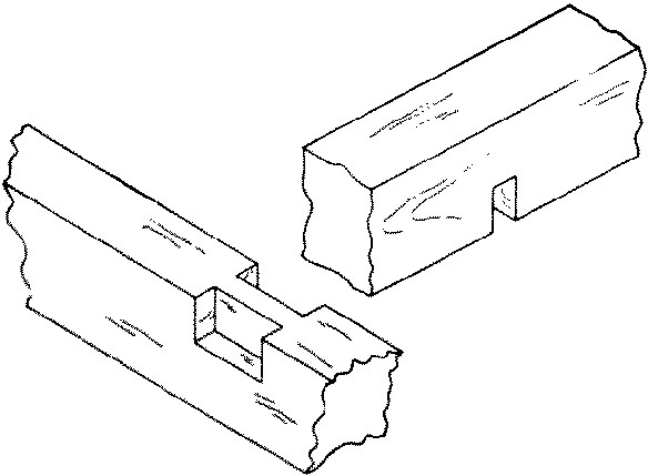
Fig. 265-22 Cogged
No. 23. A forked tenon joint is made by cutting a fork in the end of one member, and notching the other member to fit into the fork, so that neither piece can slip. It is used in knock-down furniture and in connecting a muntin to a rail, where it is desired that the muntin should run thru and also that the rail be continuous.
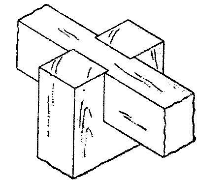
Fig. 265-23 Forked
No. 24. A rabbet or rebate or ledge joint is made by cutting out a portion of the side or end of a board or timber X to receive the end or side of another, Y. It may then be nailed from either the side or end or from both. The neatest way in small boxes is from the end, or better still it may be only glued.
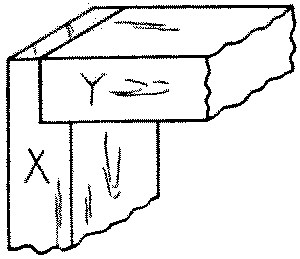
Fig. 266-24 Rabbet
No. 25. A dado or grooved joint is made by cutting in one member a groove into which the end or edge of the other member fits. Properly speaking a groove runs with the grain, a dado across it, so that the bottom of a drawer is inserted in a groove while the back of the drawer is inserted in a dado. Where the whole of the end of one member is let into the other, such a dado is also called a housed dado. Treads of stairs are housed into string boards.
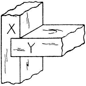
Fig. 266-25 Dado
To lay out a dado joint: After carefully dressing up both pieces to be joined, locate accurately with a knife point, on the member to be dadoed, called X, one side of the dado, and square across the piece with a try-square and knife. Then locate the other side of the dado by placing, if possible, the proper part of the other member, called Y, close to the line drawn. If this method of superposition is not possible, locate by measurement. Mark, with a knife point, on X, the thickness thus obtained. Square both these lines as far across the edges of X as Y is to be inserted. Gage to the required depth on both edges with the marking-gage.
To cut the joint: First make with the knife a triangular groove on the waste side of each line, as indicated in Fig. 91, p. 66, and starting in the grooves thus made, saw with the back-saw to the gaged lines on both edges. The waste may now be taken out either with a chisel or with a router, Fig. 122, p. 83. The second member, Y, should just fit into a dado thus made, but if the joint is too tight, the cheeks of the dado may be pared with a chisel. In delicate work it is often wise not to saw at all, but to use only the knife and chisel.
No. 26. A dado and rabbet is made by cutting a dado in one member, X, and a rabbet on the other, Y, in such a way that the projecting parts of both members will fit tight in the returns of the other member. It is used in boxes and gives plenty of surface for gluing.