

 полная версия
Handwork in Wood
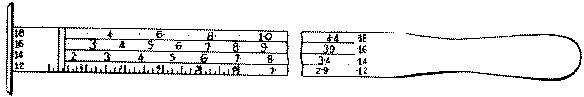
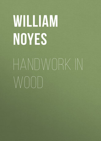
Fig. 199. Lumberman's Board Rule.
The try-square, Fig. 200, which is most commonly used for measuring the accuracy of right angles, is also convenient for testing the width of a board at various places along its length, for making short measurements, and as a guide in laying out lines with a pencil or knife at right angles to a surface or edge. The sizes are various and are indicated by the length of the blade. A convenient size for the individual bench and for ordinary use has a blade 6" long. It is also well to have in the shop one large one with a 12" blade.


In testing the squareness of work with the try-square, care must be taken to see that the head rests firmly against the surface from which the test is made, and then slipped down till the blade touches the edge being tested, Fig. 203. The edge should be tested at a number of places in the same way: that is, it should not be slid along the piece. The try-square is also of great use in scribing lines across boards, Fig. 204. A good method is to put the point of the knife at the beginning of the desired line, slide the square, along until it touches the knife-edge; then, resting the head of the square firmly against the edge, draw the knife along, pressing it lightly against the blade, holding it perpendicularly. To prevent the knife from running away from the blade of the try-square, turn its edge slightly towards the blade.
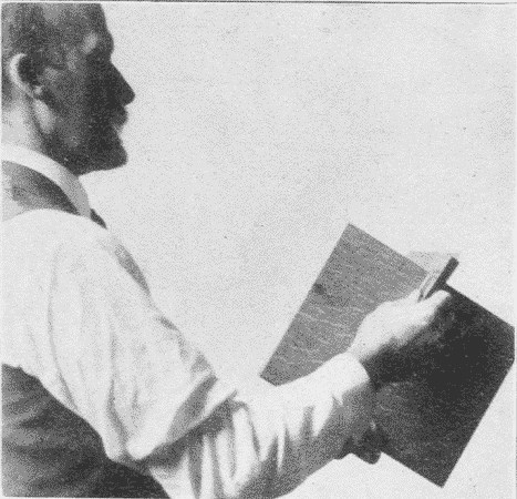
Fig. 203. Using the Try-Square.
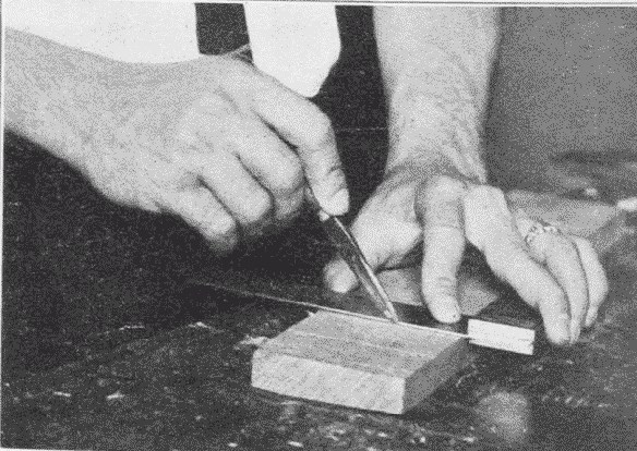
Fig. 204. Scribing with Knife by Try-Square.
The miter-square, Fig. 201, is a try-square fixed at an angle of 45°.
The sliding T bevel, Fig. 202, has a blade adjustable to any angle. It may be set either from a sample line, drawn on the wood, from a given line on a protractor, from drawing triangles, from the graduations on a framing square, or in other ways. It is used similarly to the T-square.
Winding-sticks, Fig. 205, consist of a pair of straight strips of exactly the same width thruout. They are used to find out whether there is any twist or "wind" in a board. This is done by placing them parallel to each other, one at one end of the board, and the other at the other end. By sighting across them, one can readily see whether the board be twisted or not, Fig. 206. The blades of two framing-squares may be used in the same manner.

Fig. 205. Winding-Sticks, 12 inches Long.
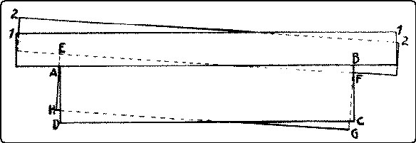
Fig. 206. Method of Using the Winding-Sticks.
Compasses or dividers, Fig. 207, consist of two legs turning on a joint, and having sharpened points. A convenient form is the wing divider which can be accurately adjusted by set-screws. A pencil can be substituted for the removable point. They are used for describing circles and arcs, for spacing, for measuring, for subdividing distances, and for scribing. In scribing a line parallel with a given outline, one leg follows the given edge, or outline, and the point of the other, marks the desired line. Used in this way they are very convenient for marking out chamfers, especially on curved edges, a sharp pencil being substituted for the steel point.
The beam-compass, Fig. 208, consists of two trammel-points running on a beam which may be made of any convenient length. It is used for describing large circles. A pencil may be attached to one point.
Calipers, outside and inside, Figs. 209, 210, are necessary for the accurate gaging of diameters, as in wood-turning.


The marking-gage, Fig. 211, consists of a head or block sliding on a beam or bar, to which it is fixed by means of a set-screw. On the face of the head is a brass shoe to keep the face from wearing. Projecting thru the beam is a steel spur or point, which should be filed to a flat, sharp edge, a little rounded and sharpened on the edge toward which the gage is to be moved, Fig. 212. It should project about ⅛" from the beam. If the spur be at all out of place, as it is likely to be, the graduations on a beam will be unreliable. Hence it is best to neglect them entirely when setting the gage and always to measure with the rule from the head to the spur, Fig. 213.
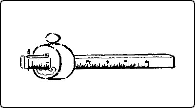
Fig. 211. Marking-Gage.
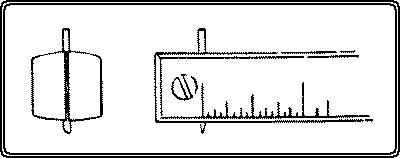
Fig. 212. Spur of Marking-Gage.
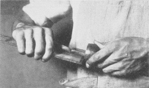
Fig. 213. Setting a Marking-Gage.
In use the beam should be tilted forward, so as to slide on its corner, Fig. 214. In this way the depth of the gage line can be regulated. Ordinarily, the finer the line the better. The head must always be kept firmly pressed against the edge of the wood so that the spur will not run or jump away from its desired course. Care should also be taken, except in rough pieces, to run gage lines no farther than is necessary for the sake of the appearance of the finished work. To secure accuracy, all gaging on the surface of wood, should be done from the "working face" or "working edge."
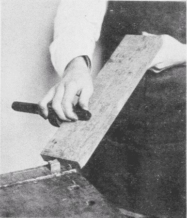
Fig. 214. Using the Marking-Gage.
It is sometimes advisable, as in laying out chamfers, not to mark their edges with a marking-gage, because the marks will show after the chamfer is planed off. A pencil mark should be made instead. For this purpose a pencil-gage may be made by removing the spur of a marking-gage, and boring in its place a hole to receive a pencil stub with a blunt point, or a small notch may be cut in the back end of the beam, in which a pencil point is held while the gage is worked as usual except that its position is reversed. For work requiring less care, the pencil may be held in the manner usual in writing, the middle finger serving as a guide, or a pair of pencil compasses may be used, one leg serving as a guide. A special gage is made for gaging curved lines, Fig. 215.
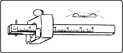
Fig. 215. Marking-Gage for Curves.
The cutting-gage, Fig. 216, is similar to a marking-gage, except that it has a knife-point inserted instead of a spur. It is very useful in cutting up soft, thin wood even as thick as ¼".
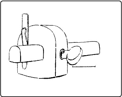
Fig. 216. Cutting-Gage.
The slitting-gage is used in a similar way, but is larger and has a handle.
The mortise-gage, Fig. 217, is a marking-gage with two spurs, with which two parallel lines can be drawn at once, as in laying out mortises. One form is made entirely of steel having, instead of spurs, discs with sharpened edges.
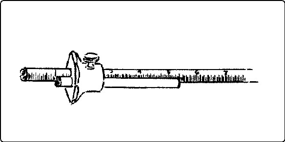
Fig. 217. Roller Mortise-Gage.
The scratch-awl, Fig. 218, has a long, slender point which is useful not only for marking lines, but for centering.
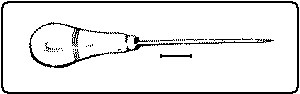
Fig. 218. Scratch-Awl.
The auger-bit-gage, Fig. 219, is a convenient tool for measuring the depth of holes bored, but for ordinary purposes a block of wood sawn to the proper length thru which a hole is bored, is a satisfactory substitute.
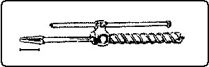
Fig. 219. Auger-Bit-Gage.
Screw- and wire-gages, Fig. 220, are useful in measuring the lengths and sizes of screws and wire when fitting or ordering.
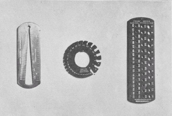
Fig. 220. Screw- and Wire-Gages. a. Screw-Gage. b. Wire-Gage. c. Twist-Drill-Gage.
The spirit-level, and the plumb-line which it has largely replaced, are in constant use in carpentering, but are rarely needed in shopwork.
Blackboard compasses, triangles, etc., are convenient accessories in a woodworking classroom.
8. SHARPENING TOOLSThe grindstone for woodworking tools is best when rather fine and soft. The grinding surface should be straight and never concave. The stone should run as true as possible. It can be made true by using a piece of 1" gas pipe as a truing tool held against the stone when run dry. Power grindstones usually have truing devices attached to them, Fig. 221. A common form is a hardened steel screw, the thread of which, in working across the face of the grindstone, as they both revolve, shears off the face of the stone. The surface should always be wet when in use both to carry off the particles of stone and steel, and thus preserve the cutting quality of the stone, and to keep the tool cool, as otherwise, its temper would be drawn, which would show by its turning blue. But a grindstone should never stand in water or it would rot.
It is well to have the waste from the grindstone empty into a cisternlike box under it, Fig. 221. In this box the sediment will settle while the water overflows from it into the drain. Without such a box, the sediment will be carried into and may clog the drain. The box is to be emptied occasionally, before the sediment overflows.
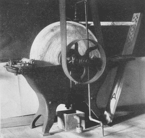
Fig. 221. Power Grindstone.
In order that the tool may be ground accurately, there are various devices for holding it firmly and steadily against the stone. A good one is shown in Figs. 221 and 222. This device is constructed as follows: A board A is made 2" thick, 6" wide, and long enough when in position to reach from the floor to a point above the level of the top of the stone. It is beveled at the lower end so as to rest snugly against a cleat nailed down at the proper place on the floor. The board is held in place by a loop of iron, B, which hooks into the holes in the trough of the grindstone. In the board a series of holes (say 1" in diameter) are bored. These run parallel to the floor when the board is in place, and receive the end of the tool-holder. The tool-holder consists of four parts: (1) a strip C, 1½" thick, and as wide as the widest plane-bit to be ground. The forward end is beveled on one side; the back end is rounded to fit the holes in the main board A. Its length is determined by the distance from the edge of the tool being ground to the most convenient hole in A, into which the rear end is to be inserted. It is better to use as high a hole as convenient, so that as the grindstone wears down, the stick will still be serviceable; (2) a strip, D, of the same width as A and ⅞" thick, and 15" to 18" long; (3) a cleat, E, ⅝" × ¾", nailed across D; (4) a rectangular loop of wrought iron or brass, F, which passes around the farther end of the two strips, C and D, and is fastened loosely to D by staples or screws.
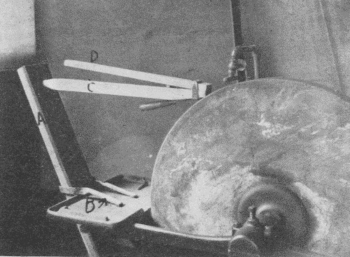
Fig. 222. Grinding Device.
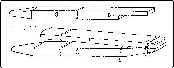
Fig. 223. Holder for Grinding Chisels or Plane-Bits.
The tool to be ground slips between this loop and the strip C, and is held firmly in place by the pressure applied to the back end of D, which thus acts as a lever on the fulcrum E.
Any desired bevel may be obtained on the tool to be sharpened, by choosing the proper hole in A for the back end of C or by adjusting the tool forward or backward in the clamp. As much pressure may be put on the tool as the driving belt will stand without slipping off.
A still simpler holder for the plane-bit only, is a strip of wood 1½" thick and 2" wide, cut in the shape G shown in Fig. 223. The plane-bit fits into the saw-kerf K, and in grinding is easily held firmly in place by the hand. By inserting the rear end of the stick G into a higher or lower hole in the board A, any desired angle may be obtained. G is shown in position in Fig. 221.
All such devices necessitate a perfectly true stone. The essential features are, to have a rigid support against which the tool may be pushed by the revolving stone, to hold the tool at a fixed angle which may be adjusted, and to press the tool against the stone with considerable pressure. The wheel should revolve toward the edge which is being ground, for two reasons. It is easier to hold the tool steadily thus, and the danger of producing a wire edge is lessened. The edge as it becomes thin, tends to spring away from the stone and this tendency is aggravated if the stone revolves away from the edge. If the stone does not run true and there is a consequent danger of digging into the stone with the tool which is being sharpened, the stone would better revolve away from the edge. The grinding should continue until the ground surface reaches the cutting edge and there is no bright line left along the edge. If the grinding is continued beyond this point, nothing is gained, and a heavy wire edge will be formed.
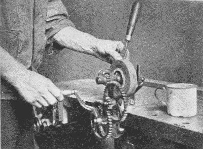
Fig. 224. Agacite Grinder.
A very convenient and inexpensive grinding tool, Fig. 224, sold as the "Agacite grinder,"11 has a number of different shaped grinding stones made chiefly of carborundum.
The oilstone. After grinding, edge tools need whetting. This is done on the whetstone, or oilstone. The best natural stones are found near Hot Springs, Arkansas. The fine white ones are called Arkansas stones, and the coarser ones Washita stones. The latter are better for ordinary woodworking tools. The India oilstone, an artificial stone, Fig. 77, p. 58, cuts even more quickly than the natural stones. It is made in several grades of coarseness. The medium grade is recommended for ordinary shop use. Oil is used on oilstones for the same purpose as water on a grindstone. When an oilstone becomes hollow or uneven by use, it may be trued by rubbing it on a flat board covered with sharp sand, or on sandpaper tacked over a block of wood.
Slipstones, Fig. 225, are small oilstones, made into various shapes in order to fit different tools, as gouges, the bits of molding-planes, etc.
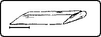
Fig. 225. Slipstone.
Files are used for sharpening saws, augers, scrapers, etc. See above, p. 90.
9. CLEANING TOOLSThe bench duster. One may be noted hanging on the bench shown in Fig. 166, p. 98. Bristle brushes for cleaning the benches are essential if the shop is to be kept tidy.
Buffer. Wherever a lathe or other convenient revolving shaft is available, a buffer made of many thicknesses of cotton cloth is very valuable for polishing tools. The addition of a little tripoli greatly facilitates the cleaning.
WOOD HAND TOOLS.—ContinuedReferences:12
(4) Scraping Tools.
Barnard, pp. 136-142.
Wheeler, pp. 465, 473.
Griffith, pp. 71-75.
Selden, pp. 149, 177, 182.
Hodgson, I, pp. 61-74.
(5) Pounding Tools.
Barnard, pp. 24-47.
Sickels, p. 70.
Wheeler, pp. 414, 428-432.
Selden, pp. 31, 111, 156.
Goss, p. 60.
Barter, p. 128.
(6) Punching Tools.
Barnard, p. 29.
Wheeler, p. 433.
Selden, p. 161.
(7) Gripping Tools.
For holding work:
Goss, p. 63.
Wheeler, pp. 65-75, 475.
Selden, pp. 140, 147, 186, 194.
Hammacher, pp. 286-291.
For holding other tools:
Goss, pp. 56-59.
Selden, p. 143.
(8) Measuring and Marking Tools.
Goss, pp. 9-20.
Griffith, pp. 9-19.
Hodgson, The Steel Square.
Wheeler, p. 465.
Tate, pp. 21-25.
Building Trades Pocketbook, pp. 234-237.
Selden, pp. 149, 150-152, 175.
Sargent's Steel Squares.
(9) Sharpening Tools.
Barnard, pp. 136-142.
Sickels, pp. 80-85.
Wheeler, pp. 480-488.
Selden, pp. 153, 162, 172, 180.
Goss, pp. 39, 64-69.
Chapter V.
WOOD FASTENINGS
The following are the chief means by which pieces of wood are fastened together: nails, screws, bolts, plates, dowels, glue, hinges, and locks.
NAILSNails, Fig. 226, may be classified according to the material of which they are made; as, steel, iron, copper, and brass. Iron nails may be galvanized to protect them from rust. Copper and brass nails are used where they are subject to much danger of corrosion, as in boats.
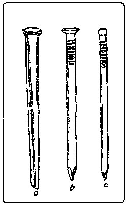
Nails may also be classified according to the process of manufacture; as, cut nails, wrought nails, and wire nails. Cut nails are cut from a plate of metal in such a way that the width of the nail is equal to the thickness of the plate, and the length of the nail to the width of the plate. In the third dimension, the nail is wedge-shaped, thin at the point and thick at the head. Unless properly driven, such nails are likely to split the wood, but if properly driven they are very firm. In driving, the wedge should spread with and not across the grain.
Wrought nails are worked into shape from hot steel, and have little or no temper, so that they can be bent over without breaking, as when clinched. Horseshoe- and trunk-nails are of this sort. They are of the same shape as cut nails.
Wire nails are made from drawn steel wire, and are pointed, headed, and roughened by machinery. They are comparatively cheap, hold nearly if not quite as well as cut nails, which they have largely displaced, can be bent without breaking, and can be clinched.
Nails are also classified according to the shape of their heads; as, common or flat-heads, and brads or finishing nails. Flat-heads are used in ordinary work, where the heads are not to be sunk in the wood or "set."
Some nails get their names from their special uses; as, shingle-nails, trunk-nails, boat-nails, lath-nails, picture-nails, barrel-nails, etc.
The size of nails is indicated by the length in inches, and by the size of the wire for wire nails. The old nomenclature for cut nails also survives, in which certain numbers are prefixed to "penny." For example, a threepenny nail is 1¼" long, a fourpenny nail is 1½" long, a fivepenny nail is 1¾" long, a sixpenny nail is 2" long. In other words, from threepenny to tenpenny ¼" is added for each penny, but a twelvepenny nail is 3¼" long, a sixteenpenny nail is 3½" long, a twentypenny nail is 4" long. This is explained as meaning that "tenpenny" nails, for example, cost tenpence a hundred. Another explanation is that originally 1000 of such nails weighed a pound. The size of cut nails is usually still so indicated. Nails are sold by the pound.
The advantages of nails are that they are quickly and easily applied, they are strong and cheap, and the work can be separated, tho with difficulty. The disadvantages are the appearance and, in some cases, the insecurity.
The holding power of nails may be increased by driving them into the wood at other than a right angle, especially where several nails unite two pieces of wood. By driving some at one inclination and some at another, they bind the pieces of wood together with much greater force than when driven in straight.
The term brads was once confined to small finishing nails, but is now used for all finishing nails, in distinction from common or flat-headed nails. The heads are made round instead of flat so that they may be set easily with a nailset and the hole filled with a plug, or, where the wood is to be painted, with putty. They are used for interior finishing and other nice work.
Tacks, Fig. 227, vary in size and shape according to their use; as, flat-headed, gimp, round-headed, and double-pointed or matting tacks, a sort of small staple. Their size is indicated by the word "ounce." For example, a two-ounce tack is ¼" long, a three-ounce tack is ⅜" long, a four-ounce tack is 7⁄16" long, a six-ounce tack is ½" long, etc. This term once meant the number of ounces of iron required to make 1000 tacks.
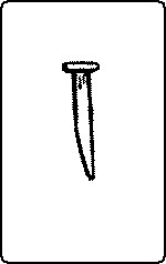
Fig. 227. Tack.
Tacks are useful only in fastening to wood thin material, such as veneers, textiles, leather, matting, tin, etc. Tinner's tacks, which are used for clinching, are commonly called clinch-nails. Wire tacks, altho made, are not so successful as cut tacks because they lack a sharp point, which is essential.
Corrugated fasteners, Fig. 228, or fluted nails, are used to fasten together two pieces of wood by driving the fastener so that one-half of it will be on each side of the joint. Their size is indicated by the length and the number of corrugations, as ½", four. They are often useful where nails are impracticable.
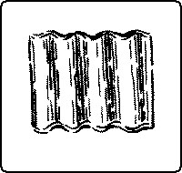
Fig. 228. Corrugated Fastener.
Glaziers' points are small, triangular pieces of zinc, used to fasten glass into sashes.
SCREWS(a) Wood-screws, Fig. 229, may be classified by the material of which they are made; as, steel or brass. Steel screws may be either bright,—the common finish,—blued by heat or acid to hinder rusting, tinned, or bronzed. Brass screws are essential wherever rust would be detrimental, as in boats.
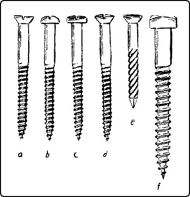
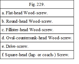
(b) Screws are also classified by shape; as, flat-headed, round-headed, fillister-headed, oval-countersunk-headed, and square-headed screws. Flat-heads are most commonly used. There are also special shapes for particular purposes. Round-heads may be used either for decoration or where great drawing power is desirable. In the latter case, washers are commonly inserted under the heads to prevent them from sinking into the wood. Oval-heads are used decoratively, the head filling the countersunk hole, as with flat-heads, and projecting a trifle besides. They are much used in the interior finish of railway cars. They are suitable for the strap hinges of a chest.
The thread of the screw begins in a fine point so that it may penetrate the wood easily where no hole has been bored as is often the case in soft wood. The thread extends about two-thirds the length of the screw. Any longer thread would only weaken the screw where it most needs strength, near the head, and it does not need friction with the piece thru which it passes.