

 полная версия
Handwork in Wood

Fig. 266-26 Dado and rabbet
No. 27. A dado, tongue and rabbet is a compound joint, made by cutting a rabbet on one member, Y, and then a dado in this rabbet, into which fits a tongue of the other member, X. It is used in machine-made drawers.
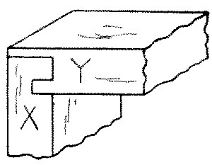
Fig. 266-27 Dado tongue and rabbet
No. 28. A dovetail dado or gain is made by cutting one or both of the sides of the infitting member, Y, on an angle so that it has to be slid into place and cannot be pulled out sidewise. It is used in book-cases and similar work, in which the shelves are fixed.
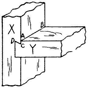
Fig. 266-28 Dovetail dado
To make this joint, first lay out the dovetail on the member to be inserted, called Y, thus: Across one end square a line (A B, No. 28), at the depth to which this member is to be dadoed in. Set the bevel-square at the proper angle for a dovetail, Fig. 250. Score this angle on the edges of the member, as at C D. Cut a groove with a knife on the waste side of A B. Saw to the depth A C, and chisel out the interior angle A C D.
Then lay out the other member, X, thus: mark with the knife the proper place for the flat side of Y, square this line across the face and on the edges as for a simple dado. Lay out the thickness of Y on the face of X by superposition or otherwise and square the face and edges, not with a knife but with a sharp pencil point. Gage the required depth on the edges. Now with the bevel-square as already set, lay out the angle A C D on the edges of X, and across the face at C score a line with knife and try-square. Cut out grooves in the waste for the saw as in a simple dado, and saw to the proper depth and at the proper angle. Chisel or rout out the waste and when complete, fit the pieces together.
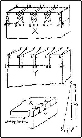
Fig. 250. Laying Out a Dovetail Joint.
No. 29. A gain joint is a dado which runs only partly across one member, X. In order to make the edges of both members flush and to conceal the blind end of the gain, the corner of the other member, Y, is correspondingly notched out. In book shelves a gain gives a better appearance than a dado.
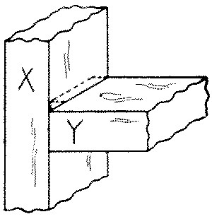
Fig. 266-29 Gain
A gain joint is laid out in the same way as the dado, except that the lines are not carried clear across the face of X, and only one edge is squared and gaged to the required depth. Knife grooves are made in the waste for starting the saw as in the dado. Before sawing, the blind end of the gain is to be chiseled out for a little space so as to give play for the back-saw in cutting down to the required depth. To avoid sawing too deep at the blind end, the sawing and chiseling out of waste may be carried on alternately, a little at a time, till the required depth is reached. It is easy to measure the depth of the cut by means of a small nail projecting the proper amount from a trial stick, Fig. 251. The use of the router, Fig. 122, p. 83, facilitates the cutting, and insures an even depth.
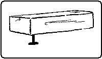
Fig. 251. Depth-gage for Dado.
MORTISE-AND-TENON JOINTS
The tenon in its simplest form is made by dividing the end of a piece of wood into three parts and cutting out rectangular pieces on both sides of the part left in the middle. The mortise is the rectangular hole cut to receive the tenon and is made slightly deeper than the tenon is long. The sides of the tenon and of the mortise are called "cheeks" and the "shoulders" of the tenon are the parts abutting against the mortised piece.
No. 30. A stub mortise-and-tenon is made by cutting only two sides of the tenon beam. It was formerly used for lower ends of studding or other upright pieces to prevent lateral motion.
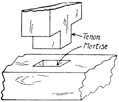
Fig. 266-30 Stub mortise and tenon
No. 31. A thru mortise-and-tenon is made by cutting the mortise clear thru one member and by cutting the depth of the tenon equal to or more than the thickness of the mortised member. The cheeks of the tenon may be cut on two or four sides. It is used in window sashes.
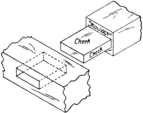
Fig. 266-31 Thru mortise and tenon
A thru mortise-and-tenon joint is made in the same way as a blind mortise-and-tenon (see below), except that the mortise is laid out on the two opposite surfaces, and the boring and cutting are done from both, cutting first from one side and then from the other.
No. 32. A blind mortise-and-tenon is similar to the simple mortise-and-tenon described in 30. The tenon does not extend thru the mortised member and the cheeks of the tenon may be cut on two or four sides.
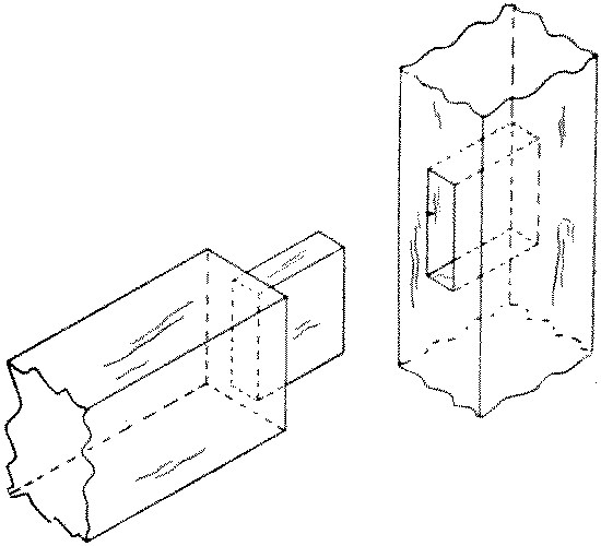
Fig. 266-32 Blind mortise and tenon
To make a blind mortise-and-tenon, first make the tenon thus: Locate accurately with a knife point the shoulders of the tenon and square entirely around the piece. On the working edge near the end mark the thickness of the tenon. Set the marking-gage at the proper distance from the working face to one cheek of the tenon and gage the end and the two edges between the end and the knife-lines. Reset the gage to mark the thickness of the tenon and gage that in the same way from the working face. Then mark and gage the width of the tenon in the same way. Whenever there are several tenons of the same size to be cut, they should all be laid out together, that is the marking-gage set once to mark all face cheeks and once to mark all back cheeks. If a mortise-gage is available, use that. Always mark from the working face or working edge. Cut out a triangular groove on the waste side of the knife lines (at the shoulders) as in cutting a dado, Fig. 91, p. 66.
In cutting the tenon, first rip-saw just outside the gaged lines, then crosscut at the shoulder lines. Do all the rip-sawing before the crosscutting. If the pieces are small the back-saw may be used for all cuts. It is well to chamfer the arrises at the end of the tenon to insure its starting easily into the mortise.
Locate the ends of the mortise and square lines across with a sharp pencil in order to avoid leaving knife marks on the finished piece. Then locate the sides of the mortise from the thickness of the tenon, already determined, and gage between the cross lines. As in the case of like tenons, if there are a number of mortises all alike, set the gage only twice for them all.
In cutting the mortice, first fasten the piece so that it will rest solid on the bench. This may be done either in a tail vise or by a handscrew, or by clamping the bench-hook firmly in the vise in such a way that the cleat of the bench-hook overhangs the piece. Then tap the bench-hook with a mallet and the piece will be found to be held tightly down on the bench. See Fig. 76, p. 58.
It is common to loosen up the wood by first boring a series of adjoining holes whose centers follow the center-line of the mortise and whose diameter is slightly less than the width of the mortise. Take care to bore perpendicularly to the surface, see Fig. 137, p. 86, and no deeper than necessary. Dig out the portions of wood between the auger holes and chisel off thin slices, back to the gage-lines and to the knife-lines, taking care all the time to keep the sides of the mortise perpendicular to the face. This may be tested by placing the chisel against the side of the mortise and standing alongside it a try-square with its head resting on the surface.
Finally test the tenon in the mortise noting carefully where it pinches, if anywhere, and trim carefully. The tighter it fits without danger of splitting the mortised member, the stronger will be the joint.
Many prefer to dig mortises without first boring holes. For this purpose a mortise-chisel, Fig. 68, p. 54, is desirable. The method is to begin at the middle of the mortise, placing the chisel—which should be as wide as the mortise—at right angles to the grain of the wood. Chisel out a V shaped opening about as deep as the mortise, and then from this hole work back to each end, occasionally prying out the chips. Work with the flat side of the chisel toward the middle except the last cut or two at the ends of the mortise.
No. 33. In a mortise-and-tenon joint on rabbeted pieces, Fig. 266, the tenon is as much shorter on one side than the other as the rabbet is wide. In Fig. 33, ab = cd.
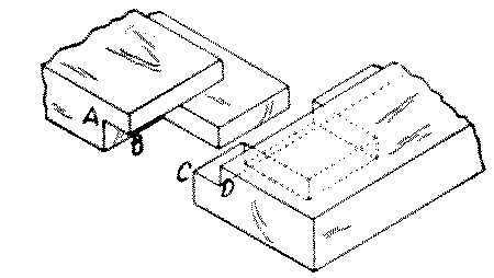
Fig. 266-33 Mortise and tenon with rabbet
No. 34. A wedged mortise-and-tenon joint is a thru joint in which after the tenon is driven home, wedges are driven in between the tenon and the sides of the mortise. The wedges are dipped in glue or white lead before being inserted. The sides of the mortise may be slightly dovetailed. It is used to keep a tenon tightly fixed as in wheel spokes.
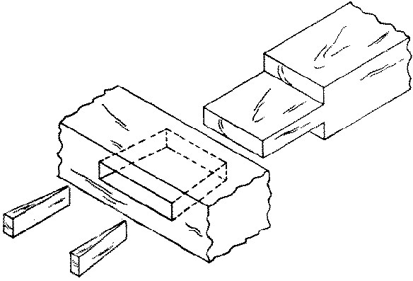
Fig. 266-34 Wedged mortise and tenon
No. 35. A wedged mortise-and-tenon joint may also be made by driving the wedges into saw kerfs in the tenon instead of along its sides as in No. 34. It is used in ornamental joints as well as in carpentry.
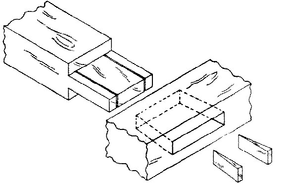
Fig. 266-35 Wedged mortise and tenon
No. 36. A fox-tail tenon is a blind mortise-and-tenon in which the mortise is made slightly wider at the bottom than the width of the tenon. Wedges are driven into saw kerfs in the tenon before inserting into the mortise; then when it is driven home the wedges spread out the tenon and make it fill out the mortise. It is used in strong doors and also where the mortised member is already in place so that a wedged mortise-and-tenon is impossible.
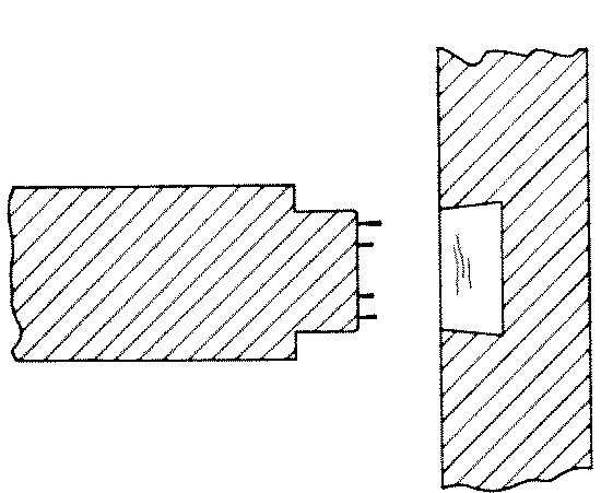
Fig. 266-36 Fox tail tenon
No. 37. A dovetail mortise-and-tenon is a thru mortise-and-tenon beveled on one side so as to form half a dovetail. The corresponding side of the mortise is also beveled and made wide enough so that when the tenon is pressed well up against its beveled side a wedge may be driven into the space left on the straight side. It is used to tenon a beam into a post especially where the post is fixed against a wall. It is also used in machinery frames which are made of wood.
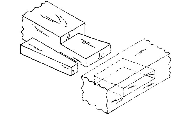
Fig. 266-37 Dovetail mortise and tenon
No. 38. A pinned mortise-and-tenon is one in which a pin is driven thru holes bored thru the mortised beam and thru the tenon to keep them from drawing apart. It is used in heavy framing as in bridges, in wagon-making, in window-sash, etc.
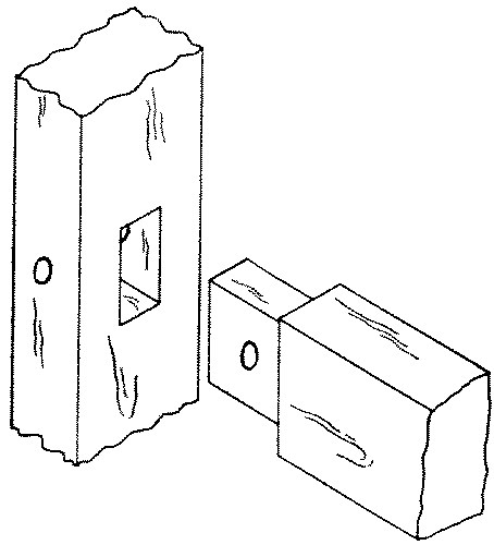
Fig. 267-38 Pinned mortise and tenon
No. 39. A keyed mortise-and-tenon is one in which the tenon protrudes thru the mortise far enough to receive a removable key and thus be drawn up tight to the mortised member. It is used in work-benches and in ornamental joints like knock-down bookcases and in other mission furniture.
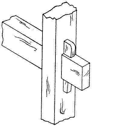
Fig. 267-39 Keyed mortise and tenon
The keyed mortise-and-tenon is made as in a thru mortise-and-tenon, except that before cutting the tenons the holes for wedges should be laid out thus: measuring from the shoulder of the tenon, locate by superposition or measurement the outside of the mortised member. Deduct from this 1⁄16" and square a fine pencil-line across the face and opposite side. This line will be the inside of the hole for the wedge, and the 1⁄16" is deducted to make sure that the key wedges against the mortised member. On the upper surface of the tenon, lay off toward the end the width of the wedge at this point, A B, Fig. 252, and square across. On the under surface, lay off the width of the wedge at this point, C D, and square across.
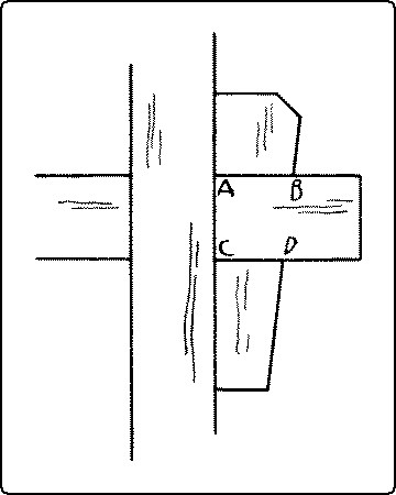
Fig. 252. Keyed Mortise-and-Tenon Joint.
Gage the sides of the wedge hole on both upper and lower surfaces of the tenon. After cutting the mortise and tenon, bore and chisel out the hole for the wedge, taking care to cut the side toward the end on a bevel to fit the wedge.
No. 40. A tusk tenon or shoulder tenon is one in which the tenon proper is quite thin but is reinforced by a thicker shoulder called a "tusk." The upper shoulder is beveled. The object of this form is to weaken the mortised member as little as possible but at the same time to increase the strength of the tenon. It is used in joining tail beams to headers in floor framing.
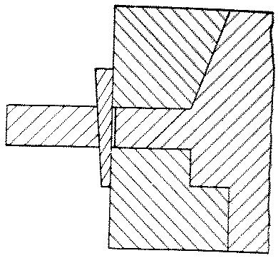
Fig. 267-40 Tusk tenon
No. 41. A double mortise-and-tenon consists of two tenons side by side in one piece fitting into two corresponding mortises. It is used in joinery, as in door-frames, but not in carpentry.
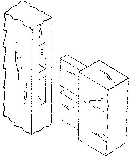
Fig. 267-41 Double mortise and tenon
No. 42. A haunched mortise-and-tenon is made by cutting away part of the tenon so that that part of it will be much shorter than the rest. The haunch gives the tenon great lateral strength and saves cutting so large a mortise hole. It is used in panel construction, as where the rails are joined to the stiles of doors.

Fig. 267-42 Haunched mortise and tenon
First plow the groove in all the members. This should be of the same width as the thickness of the tenons, which is ordinarily one-third of the thickness of the frame. The groove is approximately as deep as it is wide. Lay out and cut the tenon the width of the entire piece, minus, of course, the depth of the groove. The mortise should not come too near the end, or the portion of wood outside it will shear out. Hence the tenon is narrowed on the outside enough to insure strength in the mortised piece. The rule is that the tenon should be one-half the width of the rail, minus the groove. But enough of the tenon is left full width to fill up the groove at the outer end of the mortised piece. This is called the haunch. The width of the mortise is equal to the width of the groove, its length to the width of the tenon. Before assembling the panel frame, put soap or tallow on the corners of the panel to prevent its being glued to the frame.
No. 43. Table or taper haunching. Sometimes, as in table construction, for the sake of stiffening the rail, or in places where it is desirable that the haunch does not show, the haunch is beveled from the tenon to the edge of the rail.
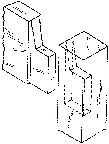
Fig. 267-43 Table haunching
No. 44. A bare-faced tenon is one in which a cheek is cut from only one side. It is used where the rail is thinner than the stile and it is desirable to keep the mortise near the middle of the stile.
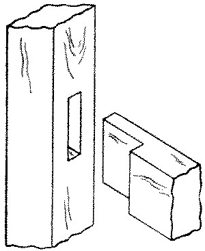
Fig. 267-44 Bare faced tenon
No. 45. A housed mortise-and-tenon is one in which the whole of the end of one member is let in for a short distance or "housed" into the other. It is common in grill work and in railings.
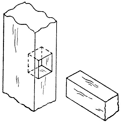
Fig. 267-45 Housed mortise and tenon
No. 46. A slip-joint or end or open mortise-and-tenon is what would remain if a mortised member were sawn off along one side of the tenoned member. Window screens and other light frames such as those for slates and for printing photographs have this joint. This joint multiplied is used for small machine-made boxes, and is then called corner locking.
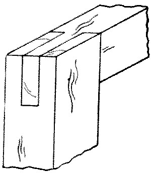
Fig. 267-46 Slip
DOVETAIL JOINTS
"Dovetail" refers to the shape of the projections of one member, when looked at broadside. These projections are called dovetails, or merely tails.
The projections on the other member are called tenons or pins, and the spaces between both tails and tenons are called mortises or sockets.
No. 47. A thru single dovetail is similar to a slip-joint except that instead of a tenon there is a dovetail. It is used in window-sashes.
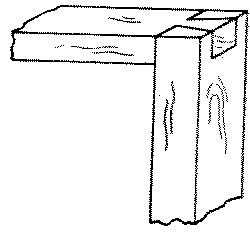
Fig. 267-47 Thru single dovetail
No. 48. A thru-multiple dovetail consists of a series of alternate tails and tenons which fit one another closely. It is used in tool-chests and in other strong as well as fine boxes.
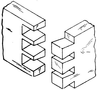
Fig. 267-48 Thru multiple dovetail
To make a thru multiple dovetail joint, first square lines with a sharp pencil around the ends of both members to locate the inner ends of the dovetails and the pins, d e on X, Fig. 250, and l m on Y. The distance of this line from the ends of each member may, if desired, be slightly (1⁄32") greater than the thickness of the other member. Divide this line, d e, on the member to be dovetailed, X, into as many equal spaces as there are to be tails (dovetails). From the division points of these spaces, a b c, to the right and left lay off one-half of the greatest width of the mortises to be cut out, and also the same distance from d and from e, as at f f f f and g g g g.
Fig. 250. Laying Out a Dovetail Joint.
(Transcriber's Note: Fig. 250. repeated here for clarity)
The strongest arrangement of dovetails is to make them equal in width to the spaces between them, as in No. 48, p. 165. For the sake of appearance they may be as much as four times as wide as the spaces, but ordinarily should not be wider than 1¾".
Set the bevel-square so that it will fit the angle A B C, Fig. 250, p. 159, in a right angle triangle, the long side of which is 3" and the short side ⅝". This is approximately an angle of 80° or a little more than one to five. From the points f f f f and g g g g lay off this angle to the end of the piece. Carry these lines across the end at right angles to the surface, h i, Fig. 250, and repeat the dovetail angles on the other surface. Mark plainly the parts to be cut out (the mortises), as on X in Fig. 250. Score with a knife point the inner ends of the mortises, d to f, g to f, etc., and across the edge at d and at e. With a dovetail-saw, Fig. 93, p. 67, cut on the mortise side of each line down to the cross line, d-e, and also along the cross line from d to f and e to g. Chisel out the mortises taking care to keep the line d-e straight and square. The ends (not the sides) of the mortises may be slightly undercut to insure a tight fit.
Fasten the other member, Y, upright in the vise so that the end to be tenoned will be flush with the top of the bench, and with the working face toward the bench. Place on it the working face of X, (the member already dovetailed,) taking care that the inner ends of the mortises are in line with the working face of Y, and that the edges of the two members are in the same plane, as X on Y in Fig. 250. Scribe with a knife point along the sides of the tails on the end of Y (f'-j' and g'-h'). Remove Y from the vise and square down these lines to the cross line l-m (j'-n and h'-o). Score with the knife point the inner ends of the mortises of Y (n-o). Saw with a dovetail-saw on the mortise sides of these lines, chisel out the mortises and fit the parts together. When glued together, the joints should be dressed off.
Where there are several parts to be made alike, it is necessary to lay out the dovetails on only one X member. This may be used as a templet for laying out the others and they can then be sawn separately. Or all the X members may be clamped carefully together, with one X already laid out, rights and lefts in pairs, and edges and ends flush, the depth mark gaged all around, and then all sawn at once.
The dovetail joint is also made by first laying out and cutting the members having the pins, and then superposing this on the piece to be dovetailed, and scribing around the pins.
No. 49. A lap or half blind dovetail is a dovetail joint in which the tails on one member do not extend entirely thru the thickness of the other member. It is used in joining the sides to the fronts of drawers and other fittings where only one side is seen.
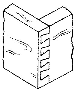
Fig. 267-49 Lap dovetail
If the joint is to be used for a drawer front, the groove for the drawer bottom should be cut or at least laid out before laying out the joint. See also drawers, p. 190, and Fig. 287, p. 191. On the end of the drawer front, gage the depth of the joint. Gage the same distance on both broad surfaces of the drawer sides, marking from the front ends. Lay out and cut the dovetails as in a thru dovetail joint, taking especial care to have the groove for the bottom completely within the lower tail. Take care also to make the sides, one right and one left, not both alike, so that the groove will come inside. Lay out the drawer front by superposing the dovetailed side, X, on the end of the front, Y, as in a thru dovetail. Saw and chisel out the mortises and fit together.
No. 50. A stopped lap dovetail is one in which neither the tails nor the pins extend thru the other members. Hence the joint is concealed. The lap may be rounded. It is used in fine boxes, trays, etc.
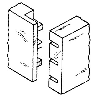
Fig. 267-50 Stopped lap dovetail
No. 51. The blind miter or secret dovetail is a joint in which only part, say one-half, of both boards is dovetailed, the outer portion being mitered. The edges of the boards are also mitered right thru for a short distance so that when finished the dovetails are invisible. It is used in highly finished boxes.
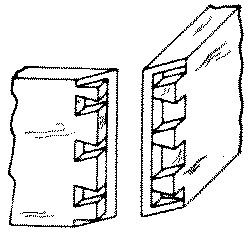
Fig. 267-51 Blind dovetail
BEVELED JOINTS
A beveled joint is made by beveling the members so that the plane of the joint bisects the angle at which the members meet. This is called the "miter" and may be 45 degrees or any other angle. It is a neat but weak joint unless reinforced by a spline, nails, or in some other way.
No. 52. A plain miter is a joint where the beveled edges or ends abut and are simply glued or nailed together. It is commonly used in picture-frames, inside trim, columns, boxes, and taborets, four or more sided.
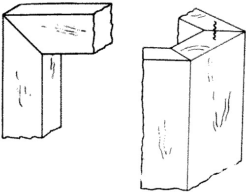
Fig. 268-52 Miter