

 полная версия
Handwork in Wood
For gluing mitered frames, the most convenient way is with the aid of the picture-frame-vise, Fig. 172, p. 101. Nails are driven or splines inserted as soon as each joint is glued. Where this vise is not available, an ordinary metalworking vise may be used, as follows: Fasten one member, X, face side up, firmly in the vise. Bore holes in the other member, Y, at the proper places for the nails. Insert nails in the holes, apply the glue to both mitered surfaces, place the glued surfaces together, letting Y project about ⅛" beyond X. A convenient way to hold Y in place is in the left hand, palm up, while the left forearm rests upon X. Drive one of the nails home, and continue driving until the parts exactly fit. Then drive home the other nail. Now fasten together in the same way the other two members of the picture-frame, and then, one at a time, the third and fourth joint. This is the method used in picture-frame factories, and when once learned is very simple.
For gluing together at once all the members of a mitered frame, the device shown in Fig. 253 is convenient and is easily made. Out of two pieces of wood somewhat longer than the two end pieces of the frame, gains are cut of the exact length of the ends, as shown in the illustration. By applying two clamps lengthwise on the frame, all four joints may be glued together at once. If the frame does not come up square, it may be squared by means of a temporary brace, A, in Fig. 253.
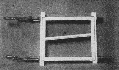
Fig. 253. Gluing Together a Picture-Frame (See also Fig. 254.)
The device shown in Figs. 254 and 255, is also an easily made and efficient tool. At least the small pieces, which receive the corners of the frame, should be made of hard wood such as maple. It is self-adjusting but care must be taken not to buckle the parts of a narrow frame by over pressure. It is well to soap or oil the corner pieces to prevent their being glued to the frame.
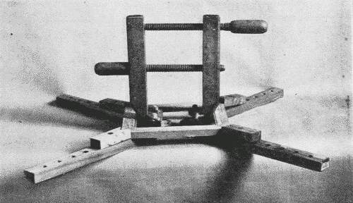
Fig. 254. Picture-Frame-Clamp.

Fig. 255. Picture-Frame-Clamp. (See also Fig. 254.)
In gluing together long mitered joints, in six or eight sided taborets or columns, in which the members meet edgewise, one method is to wrap a few turns of bale wire around the parts and drive in wedges under the wire to obtain pressure, Fig. 256. Another method is to wrap a stout rope, such as is used for window weights, around all the pieces, properly set up, then to tighten it by twisting it with a stick thru a loop, Fig. 257. A still more effective way is by means of the Noxall Column Clamp, a powerful device, used chiefly for gluing up such pieces as the pillar of a centrally supported table, Fig. 259. Care must be taken with all these devices to protect the corners, unless they are to be rounded off afterward. A good way to protect them is with pieces fastened together in the shape shown in Fig. 258, b, and Fig. 257, the interior angle being equal to the exterior angle of the piece to be glued. In the case of a taboret with slender legs, care must be taken to insert blocks between the separate legs as well, to brace them apart and to keep them from bending under the pressure. These methods have the advantage that they are speedy, since all the pieces go together at once; but unless the pieces fit exactly the joints will not close.
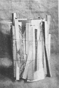
Fig. 256. Gluing up a Column Joint.
(Pinch-Dogs at Top of Joints.)
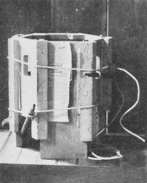
Fig. 257. One Method of Gluing up a Six-Sided Taboret.
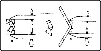
Fig. 258. Devices for Gluing Beveled Edges.
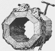
Fig. 259. Column-Clamp.
Another method is to glue and clamp the pieces of the taboret together two by two, using blocks as shown in Fig. 258, a. Care should be taken to put the pressure of the handscrews as far out as possible so as to be sure that the outside of the joint closes. This method has the advantage that, as only one joint is glued at a time, the work can be done more deliberately. Moreover, if when three pairs of a six-sided taboret are together, the other three joints do not fit exactly, they can then be refitted.
Another method is to glue pieces of soft wood on the exterior of each pieces as shown in Fig. 258, c. These blocks should be of such shape that the opposite sides of each pair are parallel. When the glue is dry, they are used as corners on which to clamp the handscrews. This method has the disadvantage that the blocks may break loose at a critical moment.
In addition to any of these methods of tightening the joints, to make sure that the ends of the joints close tight, pinch-dogs, Fig. 178, p. 102, may be driven into the end grain, and corrugated fasteners, Fig. 228, p. 125, also driven into the ends, make the joint quite secure.
No. 53. A doweled miter is one in which one or more dowels are inserted and glued into holes bored into the beveled edges. It may be used instead of nails, as in large picture frames.
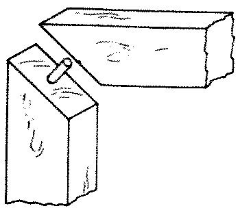
Fig. 268-53 Doweled miter
No. 54. A spline or tongue miter is one which has a spline or tongue inserted at right angles to the joint. Since it furnishes more gluing surface, it is stronger than a plain miter.
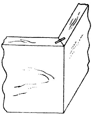
Fig. 268-54 Spline miter
No. 55. A slip-feather or slip-key miter is one which is strengthened by a slip of hardwood glued into a saw kerf cut across the mitered angle. It is used in picture-frames and in boxes.
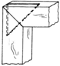
Fig. 268-55 Slip feather miter
No. 56. A slip-dovetail miter is one in which a trapezoidal shaped key is inserted in a dovetail socket cut straight across the miter. When dressed off, it gives the appearance of a dovetail on each face. It is used for the same purpose as a spline miter.
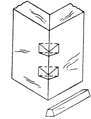
Fig. 268-56 Slip dovetail miter
No. 57. A double dovetail keyed miter is one in which a double dovetail key made of hard wood is inlaid across the joint. This is a favorite joint with Oriental joiners.
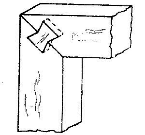
Fig. 268-57 Double dovetail keyed
No. 58. A ledge and miter or lipped miter joint is made by rabbeting and mitering the boards to be joined so that the outer portion of the two boards meet in a miter. It is strong and good looking and may be glued or nailed. It is used for fine boxes.
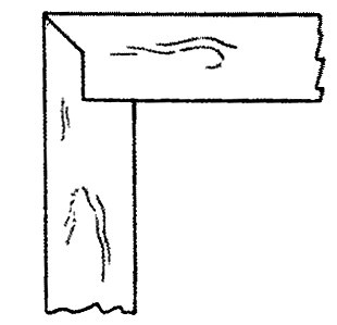
Fig. 268-58 Ledge and miter
No. 59. A stopped miter is useful for joining pieces of different widths, when both sides can be seen.
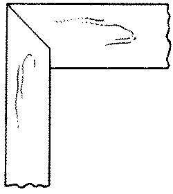
Fig. 268-59 Stopped miter
No. 60. A double-tongue miter is made by cutting on the adjoining edges tongues which engage in each other. It is used in high class joinery, on members that join lengthwise of the grain.
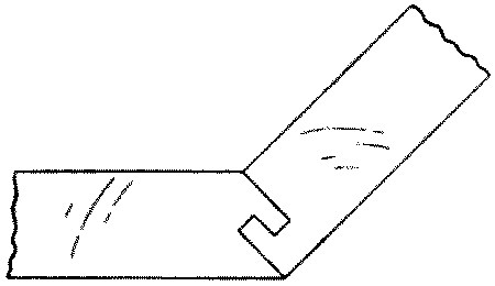
Fig. 268-60 Double tongue miter
No. 61. A stretcher joint is a slip joint in which one or both sides is mitered. It is used in frames for stretching canvass for paintings by driving wedges from the inside. Two forms are shown in 61a and 61b.
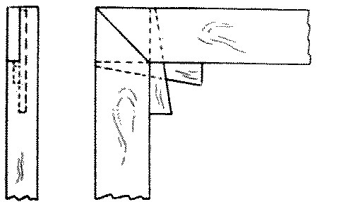
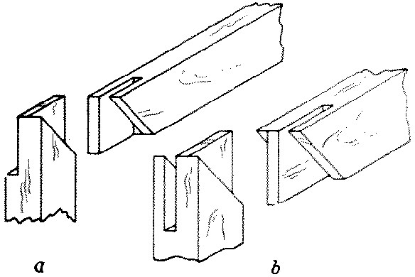
Fig. 268-61 Stretcher
No. 62. A strut joint is a form of miter joint used in making trusses.
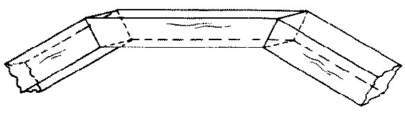
Fig. 268-62 Strut
No. 63 and 64. A thrust joint or tie joint or toe joint is one in which two beams meet at an oblique angle, one receiving the thrust of the other. The toe may be either square as in 63, or oblique as in 64. The pieces are bolted or strapped together with iron. It is used for the batter braces of bridges.
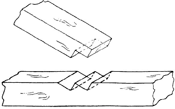
Fig. 268-63 Square thrust

Fig. 268-64 Oblique thrust
No. 65. A plain brace joint is one in which the brace is simply mitered and nailed into place. It is used for bracket supports.
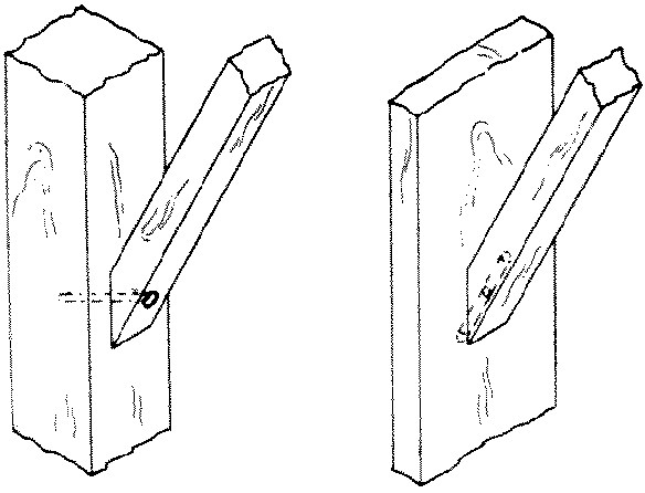
Fig. 269-65 Brace
No. 66. A housed brace joint is a joint in which the brace is housed into the rectangular members except that the outer end of the mortise is cut at right angles and the inner end diagonally to receive the brace which is cut to correspond. It is much stronger than 65.
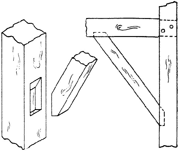
Fig. 269-66 Housed brace
No. 67. An oblique mortise-and-tenon or bevel-shoulder joint is one in which the shoulders of the tenoned beam are cut obliquely and its end is cut off at right angles. The cheeks of the mortise are correspondingly sunk. By these means the tenon prevents lateral motion while the whole width of the beam presses against the abutment. Thus a much larger bearing surface is obtained. The whole is bolted or strapped together. It is used in heavy truss work.
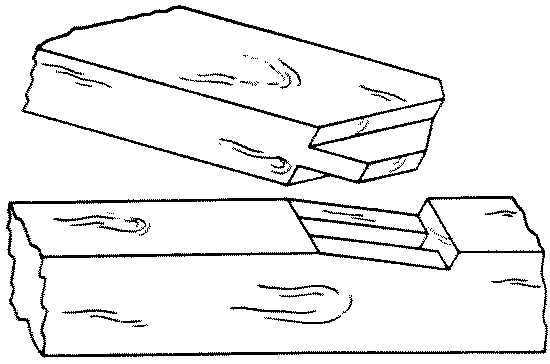
Fig. 269-67 Oblique mortise and tenon
No. 68. A bridle joint is an oblique joint in which a bridle or "tongue" is left in an oblique notch cut out of one beam. Over this tongue is fitted a grooved socket cut obliquely in the other beam. It is used in truss construction.
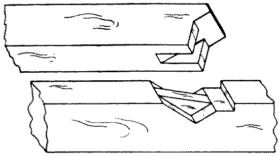
Fig. 269-68 Bridle
No. 69. A bird's mouth joint is an angular notch cut in a timber to allow it to fit snugly over the member on which it rests. It is used in rafters where they fit over the plate.
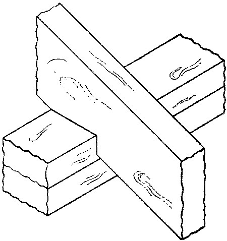
Fig. 269-69 Bird's mouth
No. 70. A plain or rubbed or squeezed or glue joint is one in which the edges of two boards are glued and rubbed together tight. It is used in table-tops, drawing-boards, etc.
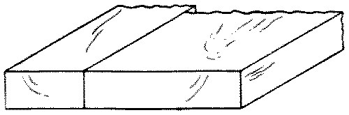
Fig. 269-70 Glue
To make this joint, first the boards are all laid down flat, side by side, and arranged in the proper order. Three considerations determine what this order is to be: (1), if the grain is of prime importance, as in quartered oak, then the boards are arranged so as to give the best appearance of the grain. (2), if possible, the boards should be so arranged that the warping of each board shall counteract that of the adjacent ones. For this purpose the boards are so laid that the annual rings of one shall alternate in direction with the annual rings of the next, Fig. 280, a, p. 186. (3), if possible, the boards should be so arranged that after being glued together they can all be planed smooth in the same direction. When the above requirements have been met so far as possible, this order should be marked on adjoining edges for later identification. The edges of the boards to be joined should be finished with a jointer.
There are two principal methods of gluing edge-to-edge joints, rubbing and squeezing. In a rubbed joint, the surfaces to be joined should be planed so as to meet thruout exactly. After properly planing one edge of each board, keep one board in the vise, jointed edge up, and place its to-be neighbor in position upon it. Then use these four tests for an exact fit. (1) Sight down the end to see that the faces lie in the same plane. (2) Examine the crack from both sides. Be sure that both ends touch. Test this by pulling down hard on one end of the upper board and noticing if the other end is still in contact. If the other end opens, swing the upper board horizontally on the lower board to see where the high place is and then correct it. (3) See if the upper board stands firmly on the lower board by feeling gently to see if it rocks, or by rapping lightly the lower board. (4) Slide the top board slowly on the lower one to see if it adheres or "sucks."
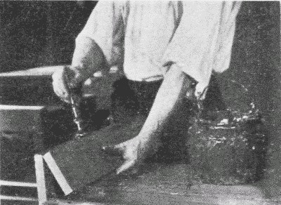
Fig. 260. Applying Glue for an Edge-to-Edge Joint.
After the pieces have been warmed, which should be done if possible, the glue is spread on them, Fig. 260, and they are then rubbed slowly back and forth in the direction of the grain, pressure being applied by the hand and care being taken not to open the joint in the least. As the glue sets, the rubbing becomes more difficult. It should be stopped when the boards are in their proper relative positions. In rubbing together the edges of two boards, handscrews may be fastened to one in such a way that their jaws serve as guides for the other board to slide between, Fig. 261. Care must be taken to make the jaws of the handscrew diverge enough not to pinch the upper board.
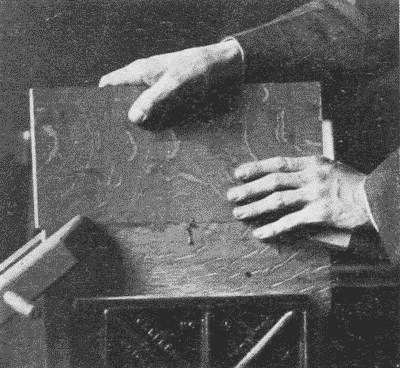
Fig. 261. Rubbing a Glued Joint.
Another method is to clamp a spare board alongside and projecting above the lower board. This spare board acts as a guide against which the upper board can be pushed as it is rubbed back and forth. The rubbed joint is especially suitable for short boards.
In joining long boards, a squeezed joint is common. In this case, the edges are planed so as to be very slightly concave from end to end. The object of this is to counteract the subsequent shrinkage which is likely to take place at the ends of the boards before it does at the middle. The pressure of the clamps may be depended upon to close up the middle, and, especially if dowels are inserted, as in No. 75, the joint will be strong enough to resist the elasticity of the boards.
When the fit is good, warm the wood if possible, prepare the clamps, put a thin film of glue over both edges which are to be together, apply the clamps rapidly, keeping the faces flush, and set away to dry for at least six hours. Then another piece may be added in the same manner. If the boards are thin and wide, and therefore likely to buckle, they may first be handscrewed to cross-strips to prevent their buckling. The cross-strips are, of course, slightly shorter than the combined width of the boards so that the full pressure of the clamps may come on the glued joint.
No. 71. A rebated, rabbeted or fillistered joint. Rebating is the cutting of a rectangular slip out of the side of a piece of wood. The re-entering angle left upon the wood is called the rebate or rabbet. A rebated joint, then, is one in which corresponding rebates are taken off edges so that the joined boards may overlap. It is used in flooring and siding.
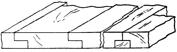
Fig. 269-71 Rabbeted
A board is rebated and filleted when two adjoining rebates are filled with a fillet.
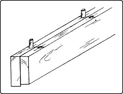
Fig. 262. Edge-to-Edge Joint, Doweled.
No. 72. A matched or tongue-and-groove joint is made by making a projection or "tongue" in the center of the edge of one board, and a corresponding groove in the center of the other so that they will match together. When used for flooring, the lower side of the grooved board is slightly rebated so that the upper edges will surely touch. This sort of flooring can be blind-nailed.
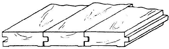
Fig. 269-72 Matched
No. 73. A beaded joint is similar to a matched joint except that a bead is worked on one edge to disguise the joint for decorative purposes.
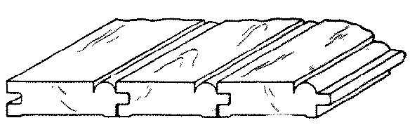
Fig. 269-73 Beaded
No. 74. A spline-joint is made by plowing corresponding grooves in the edges to be joined and inserting a spline or slip-feather. It is used in plank flooring.
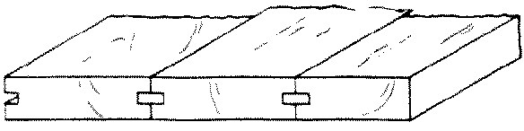
Fig. 269-74 Spline
No. 75. A doweled joint is made by jointing the two edges carefully, boring holes opposite each other and inserting dowel pins when the two edges are glued together. It is used in table tops, etc.
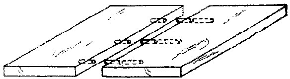
Fig. 269-75 Doweled
Where the boards are thick enough to allow it, a squeezed joint is greatly strengthened by the insertion of dowels.
The essential point in inserting dowels is to have the holes for them directly opposite one another and at right angles to the surface. The following is a convenient method where boards are to be joined edge to edge, Fig. 262. Place the two boards back to back in the vise with the edges and ends flush. Determine approximately where the dowels are to be inserted. With the gage, mark short lines at the points of insertion in the center of each edge, gaging from the outside faces. Across these lines score accurately with a try-square and knife. Then bore the holes with a dowel-bit at the intersection of the lines, Fig. 263. If this is carefully done, the holes will be directly opposite one another, and equidistant from the faces of both boards. All the holes should be of equal depth, say 1", in order that the dowel-pins, which should also be cut of equal lengths, may be interchangeable. After boring, the holes may be slightly countersunk in order to insure a tight joint and the easy slipping of the pins into place. The latter result may also be obtained by slightly pointing the pins with a dowel-pointer, Fig. 123, p. 83. It is also a wise precaution to cut a small groove along the length of the pin to allow superfluous glue to escape from the hole. The dowel should be dipped in glue and inserted when the glue is applied to the joint.
Fig. 263. Boring for Dowels in an Edge-to-Edge Joint.
THE COMMON JOINTS
References17
Rivington, Vol. I, pp. 57-77, 135-137, 238-242; Vol.II, pp. 291-295.
Adams, pp. 1-30.
Sickels, pp. 86-124.
Goss, pp. 128-152.
Ellis, pp. 135-151.
Barter, pp. 211-275.
Selden, pp. 56-130.
Building Trades Pocketbook, pp. 217-221, 237.
Griffith, pp. 86-104, 164-170.
1 Lapped and Strapped
2 Fished
3 Fished and keyed
4 Spliced for compression
5 Spliced for tension
6 Spliced and Tabled
7 Spliced for cross strain
8 Dowelled butt
9 Toe-nailed
10 Draw-bolt
11 Plain butt
12 Glued and blocked
13 Hopper
14 Cross lap
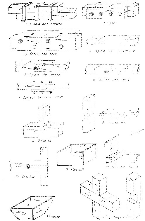
Fig. 264
Fig. 265
15 Middle lap
16 End lap
17 End lap with rabbet
18 Dovetail halving
19 Beveled halving
20 Notched
21 Checked
22 Cogged
23 Forked
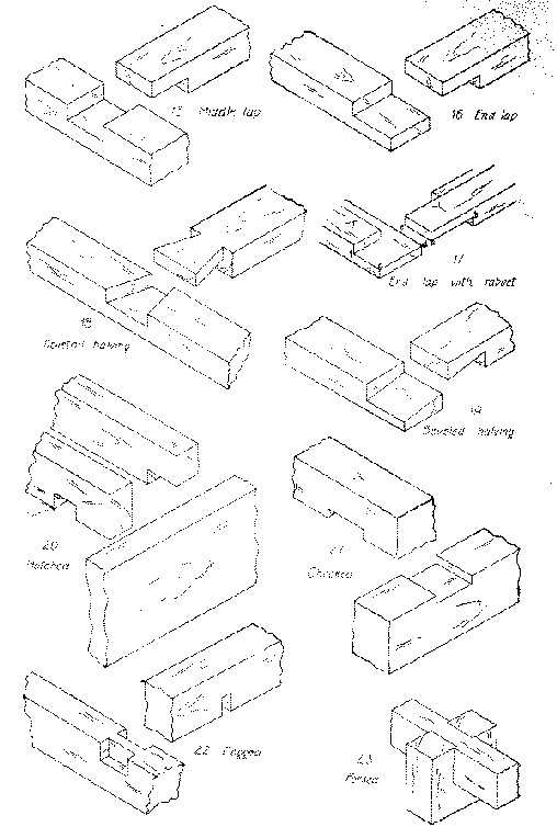
Fig. 265
Fig. 266
24 Rabbet
25 Dado
26 Dado and rabbet
27 Dado tongue and rabbet
28 Dovetail dado
29 Gain
30 Stub mortise and tenon
31 Thru mortise and tenon
32 Blind mortise and tenon
33 Mortise and tenon with rabbet
34 Wedged mortise and tenon
35 Wedged mortise and tenon
36 Fox tail tenon
37 Dovetail mortise and tenon
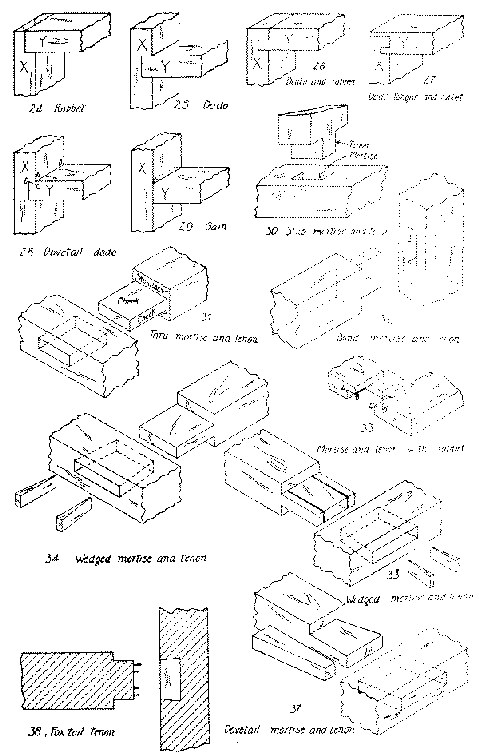
Fig. 266
Fig. 267
38 Pinned mortise and tenon
39 Keyed mortise and tenon
40 Tusk tenon
41 Double mortise and tenon
42 Haunched mortise and tenon
43 Table haunching
44 Bare faced tenon
45 Housed mortise and tenon
46 Slip
47 Thru single dovetail
48 Thru multiple dovetail
49 Lap dovetail
50 Stopped lap dovetail
51 Blind dovetail
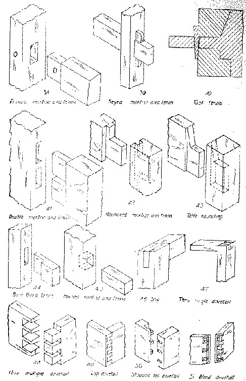
Fig. 267
Fig. 268
52 Miter
53 Doweled miter
54 Spline miter
55 Slip feather miter
56 Slip dovetail miter
57 Double dovetail keyed
58 Ledge and miter
59 Stopped miter
60 Double tongue miter
61 Stretcher
62 Strut
63 Square thrust
64 Oblique thrust
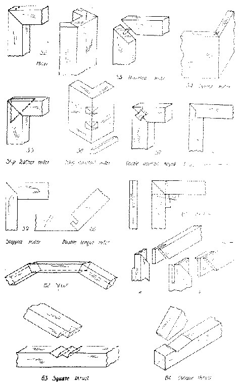
Fig. 268
Fig. 269
65 Brace
66 Housed brace
67 Oblique mortise and tenon
68 Bridle
69 Bird's mouth
70 Glue
71 Rabbeted
72 Matched
73 Beaded
74 Spline
75 Doweled
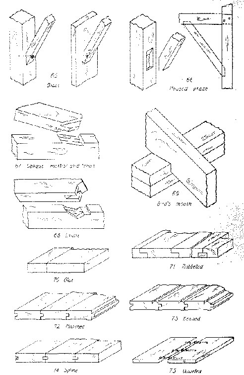
Fig. 269
Chapter VIII.
TYPES OF WOODEN STRUCTURES
The articles suitable to be made in wood with hand tools may for convenience be divided into four general classes: (1) Unjoined pieces; (2) board structures; (3) panel structures; (4) framed structures. A few illustrations of each class are given below.
(1) SIMPLE OR UNJOINED PIECESOf these there are a number that are advantageous for the learning of tool processes; at the same time they give opportunity for expression in design, and when finished are of use.
Examples are: key-boards, chiseling-boards, bread-boards, sleeve-boards, ironing-boards, coat- and skirt-hangers, and gouged trays. Some of these are so simple as to include hardly any process but planing, directions for which are given above, p. 72.
Fig. 270. Pen-Tray.
Where there is more than one process involved, the order of procedure is of importance. In general, a safe rule to follow in each case is to plane up the piece true and square, or, in technical language, to "true" it up. At least as many of its surfaces should be trued as are necessary for the "lay out." Where the piece is to be rectangular all the surfaces should be true; where some of the surfaces are to be curved it is unnecessary and a waste of time to square them first. For example, in making a gouged tray with curved outline, Fig. 270, the working face, the working edge, and the thickness should all be true before the plan is laid out. Then, after the outline is drawn, the trough may be gouged, the outline cut with turning-saw, chisel, and spokeshave, and the edges molded with the gouge or chisel. If there is incised decoration it should be cut before the molding is cut, so that while being incised, the piece will lie flat without tipping.