Полная версия
Life and Science. Popular exposition

Italy. Done and Forgotten. The main point: the neutrinos generated by the reactor are flying too fast. Faster than light
Russia. Ridiculous experiment on good equipment. It is possible to measure the speed of light “pushed” by the emitting particles directly using high-speed oscilloscopes. Russian scientists don’t
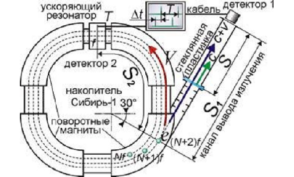
Here’s another experiment. It was held in Russia. The results are presented by the journal “Science and Life”, No. 8, 2011. Already something, in my opinion, is close to the truth. But, not really. Here is a particle accelerator. The particles spin at tremendous speeds (in one direction only) and emit light as they move. This accelerated light is diverted into a special window and… what do you think? Is its speed measured directly? This is quite possible in this experiment. Not at all. Experimenters introduce a glass plate into the path of the beam, and thus prove that the speed of light does not change when passing through a screen (analogue of ether?).
For what? Everything is much simpler.
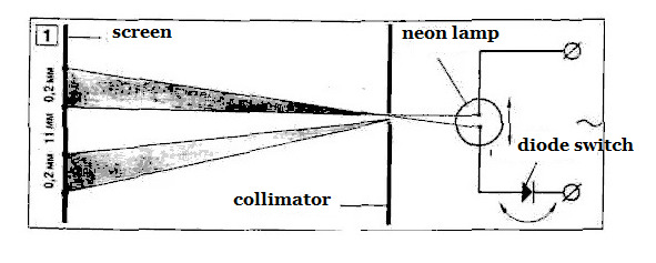
Long before that, the author was involved in measuring the speed of light, “pushed” by microparticles. Normal white light bulb. There are those in your work. Ions rush in it at a speed that can be compared with light. With the help of a diode, we make the particles fly in one direction of the tube, then in the other. I don’t have superfast sensors and high-speed oscilloscopes. Therefore, we simply project the image of the lamp onto the screen using a pinhole camera (a hole in the shield). If the quanta have a longitudinal velocity component, the image should shift. And so it happens.
This experiment, in contrast to the experiment with the synchrophasotron, you can repeat yourself
For those who love details. Based on the articles of the author in the journal “Tekhnika-Molodezhi”, No. 10, 2001, and No. 3, 2002.
“… In a household fluorescent lamp, the plasma temperature is on the order of tens of thousands of degrees. This corresponds to the motion of charged particles with a speed of about 1000 km / s. The photons emitted by ions flying with a speed V must have a speed C + V directed along the axis of the lamp parallel to the screen, in accordance with the classical principle of adding speeds, and not with the SRT formulas. If so, the spot will move in the direction of the movement of the ions emitting light. If the second postulate of SRT is true, there will be no displacement. I am using a neon lamp with a glass shell that is transparent to UV radiation. The light from the emitter passes through a narrow diaphragm and hits a screen located parallel to the plane of the emitter electrodes at a distance of 0.8 m. The direction of the current can be changed using a diode. An image of a lamp appears on the screen… When the direction of the current changes, it shifts in the direction of ion movement by 11 mm. This means that the speed of light C is added to the speed of movement of the source V according to the “ballistic” principle. According to indirect estimates, the ion velocity is 2000 km / s. This is in good agreement with the experimental results. Therefore, either the second postulate of SRT is incorrect, or its meaning needs special clarification.
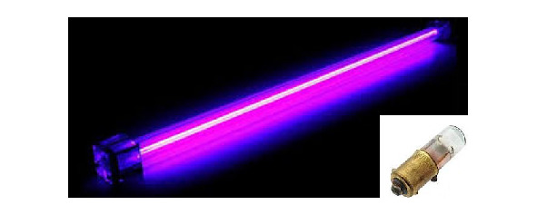
Home laboratory instrumentation – mercury and neon lamps instead of synchrophasotron
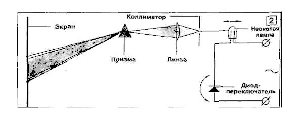
Experience with polarity reversal and prism
As they say, to seek is to seek, and therefore I set up a second experiment with a neon lamp, changing the conditions. The main element is now a prism that deflects light rays of different wavelengths in different ways. If the speed of light is greater than C, the spectrum shifts towards the violet side. If less than C, a “redshift” occurs, as when observing a receding radiation source. And this is not the Hubble effect. I place the neon lamp so that the plane of the electrodes is perpendicular to the pinhole screen. When the lamp is turned on, a spot of light appears on the screen. After polarity reversal, the beam is shifted by 24 arc minutes. Using the well-known formulas, we calculate that in this case the change in the speed of light is 520 km / s, with an error of 85 km / s.
I draw your attention to the fact that the change in the refractive index of the prism due to the different speed of the photons in the ray incident on the glass is usually masked by the property of the refractive medium. The refractive index, precisely because of the differences in the speed of quanta in vacuum (air), depends little on color, and is abnormally large. This experience is based on rather subtle assumptions, and does not have sufficient clarity. It would be more correct to use two low-inertia photosensors placed along the pulsating beam and connected to high-speed oscilloscopes. Reversing the polarity of the lamp would reveal the whole truth, which of the rays flies faster. Once and for all. The author does not have such tools.
Search for ether. Search everything
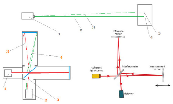
Michelson-Morley interferometer. 1. Light source 2. Screen for observing the interference pattern. 3. Beam reflected perpendicular to the interferometer arm and deflected by the ether flow to the left. 4. A ray emitted towards the stream of ether and therefore participates in the construction of an interference picture. 5. Beam reflected from the mirror of the interferometer arm, presumably directed along the ether stream. Figure above. Author’s experience with laser beam deflection. 1. Laser. 2. Laser beam at 9 am. 3. Beam at 17 o’clock. The angle is increased for clarity. 4. Place the mark on the screen at 9 o’clock. 5. Mark at 17 o’clock. The screen and the laser are separated by 90 m. The difference in the position of the beam on the screen, over five days, is 3 cm.
…Does ether exist, this kind of ocean in which light waves roll? And, as we assume, keeping the shadows of the past quite fresh, forever? Let’s bring a revision of physics. Michelson-Morley interferometer. The beam is divided by a translucent mirror. One of them goes towards the stream of ether, then back. Its speed changes. The second is perpendicular to the flow and therefore serves as a standard of speed. If the speeds do not match, the interference pattern will change. In the figure below on the left, the author imagines that the position that the rays pass strictly perpendicular paths is incorrect. During the stroke along the arms of the interferometer, the rays are deflected by the ether stream. The detector receives waves initially deflected towards the ether stream. The scheme for constructing a real interference pattern is much more complicated than Michelson’s drawings. In addition, according to the reasoning about the Mössbauer effect, only light with a “standard C” speed of 300,000 km is clearly observed. from. Figure above the interferometer. The author’s experience. The deflection of the laser beam, presumably due to entrainment by the ether. If the ether is carried away by light, with the specified parameters, the flow velocity of the medium is 100 km. from. This value is in good agreement with the speed of the Earth’s revolution around the center of the Galaxy, 200—220 km. with.. Why didn’t you notice earlier? When operating laser communication systems, the system is “zeroed” automatically or manually. This rule is considered the norm. A more plausible explanation. During the day, the air in the room where the experiments are carried out warms up. The air lens distorts the beam.
An Interferometer for the Poor. And it’s not even an interferometer
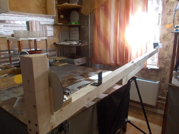
…Several years later, I decide to repeat this experience. The deviation of the beam obtained in the preliminary sample is large enough to try to create an “interferometer for the poor”, with the ability to change the direction of scanning the ether manually. On a massive bar, parallel mirrors and a laser sight are placed. The length of the beam reflected twice is 6.5 meters. It is inconvenient to turn the device and observe the change in the position of the beam at the same time. To record the results, an electronic camera rigidly fixed on a bar (not shown) is used.
…First, we reproduce a stationary experiment. We send the beam not to the lens, but to the laboratory wall. This increases the length of the light path to 10 meters. It all fits together. After 5 hours, the light spot shows a new position, 4 millimeters below. It is alarming that after a day, that is, the Earth’s rotation around the axis, it does not return to its original mark.
We pass to independent turns of the “interferometer”, without the help of the planet.

The brightness of the laser light changes when the device is turned
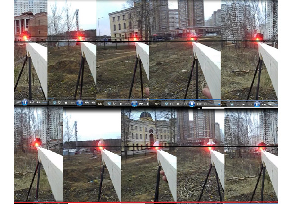
The action takes place late in the evening. The first picture, a scan of continuous video filming – the beam comes from the East (although it changes direction twice more, reflecting from the mirrors). The above images do not show the mesh imposed by the Point editor. However, I see that the vertical line formed by the beam in interaction is likely to shift with the optics of the camera. From the series of scans, for demonstration in the book, we select the most characteristic ones. East, North-East, West, East again. The beam takes on the greatest brightness when oriented to the West. The only reliable, well reproducible result that is not ashamed to present to you, dear reader, is the brightness of the glow.
We can exclude mirrors from the experiment and get a kind of elementary optical pair. The beam only goes in one direction. The result is the same.
…Indeed, propagating against the ether, or along the flow, the light accordingly loses and gains energy. Changing the direction of the beam is more difficult. Although it also exists.
Two similar outdoor experiences. Determination of beam deflection (brightness is not considered due to external uneven illumination). Directions – North, East, South, West, origin – North
…We go out into the fresh air and continue our experiments. Some researchers believe that the ether can be slowed down, and completely brought into a state of relative rest, by such an obstacle as a simple window glass.
The result is the same in both cases. Within a few minutes after switching on, the laser beam goes down by 1, 5 – 2 millimeters.
…All this, coupled with the oddities of the device settings, which would take too long to talk about here, leads to the idea that one should look for the reasons elsewhere. To do this, you need to take a step aside.
Searching for light. Step to the side
The basic idea is that the laser beam experiences a kind of attraction from a plane-parallel surface. In this case, the surface of the bar. Or the floor of the room. And with gravitational attraction there is no kinship here.
Physics textbooks initially have serious questions. What is the width of a visible light photon? Officially half of its wavelength. That is, two ten-thousandths of a millimeter. However, light is deflected by interference gratings and just tenths of a millimeter holes. The difference is a thousand times. What makes a photon feel the presence of atoms at the edge of an obstacle? What long-range action do these forces have? Has anyone checked whether the photons are deflected by the edge of the screen, located at a distance from the beam one millimeter… centimeter, or maybe a meter? Does the interaction take place right away, or does it take time for preliminary adjustment of light and matter?
As said, these experiments are a step aside. They were carried out without enthusiasm. But, nevertheless, they gave food for thought.

Diffraction classics. Diffraction from a thin wire, round hole, round opaque screen. Note the discrete, cluster pattern of light diffracted by the wire.
…Most of all, when preparing for new experiments, I was interested in the nature of interference. How so? Do light waves collapse in superposition? Are they annihilating, or what? Physics textbooks tell about this rather vaguely. No, they do not disappear. The energy conservation law is in order. The strength of the waves from the dark part of the screen appears in the light one.
Once again, comrades academicians – sorry, we did not understand. Here, these are your drawings. The course of the electromagnetic waves is clearly shown here. They are in the dark zone – there are! But they are not visible. From the word “absolutely”. Where did they go?
And the fairy tale about the white bull begins all over again.
Leaving aside the subject of long-range action of the edges of obstacles for later, I decided to take a closer look at the interference.
…The paradigm of modern science – light and dark zones of the interference pattern are formed by superposition of electromagnetic waves. There are serious questions here (see above). Why not imagine that the edges of objects themselves distribute the light in their chosen directions? Well, or, forgive me, the clouds of ether accumulated near them. In bodies there is a discrete distribution of microparticles – elementary emitters. They can deflect the beam in selected directions, creating only the appearance of interference. Is there nothing to do with classical superposition?..
The first thing that surprised me when I took up the experiments was that light not only bends around an obstacle, but also repels from it. The books confirmed what had previously slipped past consciousness. The edge scatters light in all directions. Which is quite consistent with the hypothesis of a material beacon that sends out photons in the chosen directions.

Diffraction. The edge of the obstacle sends out photons in opposite directions. Elementary, but incomprehensible
Now carefully, dear reader. We create screens from various materials, expose them to the beam and observe the interference pattern. According to the above calculations, the picture is made up of the interaction of lighthouses. The edges of the objects “agree” in which directions the light should be emitted. There are zones in which to send photons, according to the law of conservation of energy is prohibited. If the screens are made of different materials, the “interference” pattern they create will be different. Or it won’t be at all. These transmitters operate at different frequencies and therefore cannot match the light distribution.
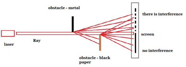
Experience in interference from screens with different physical and chemical composition
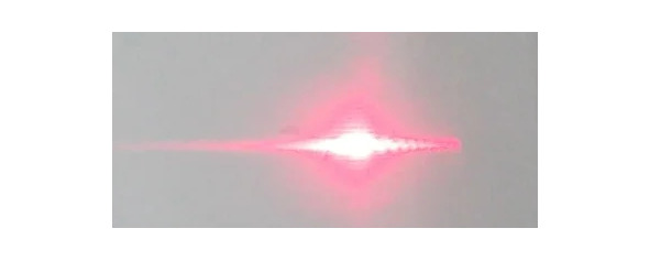
The usual interference pattern at the intersection of the fan of rays from the edges of obstacles (right half)
…No differences were found in the patterns of interference fringes when screens made of different materials were combined. The hope was for a complete, even demonstrative absence of interference lines in the area of overlapping “dissimilar” rays. It was not possible to identify differences in the distance between obstacles up to 40 cm. Presumably, the distance at which our “beacons” stop communicating with each other is too great for a home laboratory…
…The interference from the edges of opaque liquids was investigated. And in this case, the interference pattern is formed clear, and immediately.
Interference at the boundaries of biological objects, from slices of root crops, such as potatoes, apples and beets, has been investigated.
The classical principle of interference as a superposition of electromagnetic waves confirms its reputation.
But it is not exactly

…Dear reader! In this book, the experiments are presented as if the author performs them in order, in accordance with a certain, previously prepared scheme. This is not true. All life, including science, is a mixture of assumptions, experiments carried out at different times, combined for the convenience of our reading. The experiment described below was carried out one of the first, in the mid-1990s. Even then, my youthful curiosity was tormented by the question of where the waves crossed in antiphase go. Air, water or electromagnetic – in general, it doesn’t matter. So where?
Not finding the answer in various kinds of manuals in physics, the author turned to experience. He was not alone in his doubts. This, perhaps my first article was published. I present the revised version.
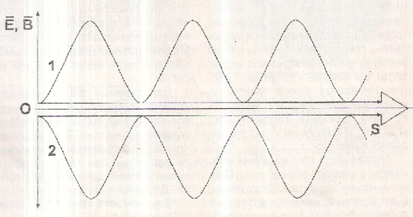
Electromagnetic waves in antiphase. For convenience of presentation, only one component of the beam is shown
So friends, let’s imagine that we took two single-color beams from good lasers and crossed them at a negligible angle (see Fig.). In antiphase. What should happen in this case?
The light… will disappear.
Logically, this is how it happens. But physics is above linear logic. Moreover, it is even higher than higher mathematics. Material objects do not at all want to be added, subtracted and multiplied in some way. They are what they are. And with this, as well as with the temper of a capricious wife, given to you forever, in joy and sorrow, you have to put up with.
The measure of truth is a natural experiment. Therefore, having swayed a little, I proceed to physical experiments.

Experience with “black light”
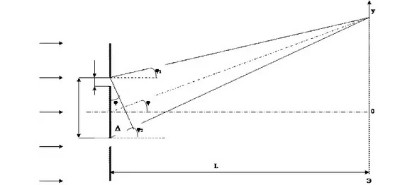
Take a look at the picture, curious reader. Number (3) indicates a source of coherent light, a laser pointer. (4) – diffraction grating. Here the light is split into many coherent rays. If you put a piece of paper in the path of this mixture, we will see a speckle. That is, a set of black and white (or, indeed, red and black) dots, similar to what we see on an unset TV screen. In the black areas, according to textbooks, the crossed beams (1,2) are added in antiphase. And, therefore, they disappear for a while for the world.
What if, in such an invisible state, light completely ceases to interact with gross matter? In particular, with hitherto impenetrable screens? Having passed the prescribed paths without any extinction, the rays go out of each other and appear to the astonished observer as if emerging from the void?!..
…We charge the camera (7) with a film of 400 light sensitivity units. Instead of a lens, we have a tube (6). The obstacle in the path of light is metal foil. We turn on the laser, open the shutter for a few hours. We expect that the paired rays, having overcome the screen in the region of space (5), will disperse inside the tube and illuminate the photographic film. It would be interesting. Something like an X-ray with light in the optical range.
But the miracle did not happen. Photos turned out without flare.
…The beams do not stack in antiphase. One wave with its “top” does not close the “bottom” of another. Where there is darkness, there is simply nothing. Physics textbooks indicate something like this, contradicting themselves, and not revealing the essence of the phenomenon.
Let’s try to formulate the unsaid.
The rays, or what looks like that, are distributed in space by the diffraction grating itself. It is this wonderful set of identical “rods” that decides where the light will be and where the darkness will be.

Classic experiment with diffraction
The addition of light waves. This is indicated in physics textbooks. At one angle, the waves add up in antiphase, creating darkness. At a different angle, they reinforce each other. In fact, the question of where the light will be and where the darkness will be is decided earlier. The lattice itself. Which is supposed to have many wonderful properties.
Конец ознакомительного фрагмента.
Текст предоставлен ООО «ЛитРес».
Прочитайте эту книгу целиком, купив полную легальную версию на ЛитРес.
Безопасно оплатить книгу можно банковской картой Visa, MasterCard, Maestro, со счета мобильного телефона, с платежного терминала, в салоне МТС или Связной, через PayPal, WebMoney, Яндекс.Деньги, QIWI Кошелек, бонусными картами или другим удобным Вам способом.