

Полная версия
Myocardial torsion
This situation generates a tangle of fibers that allows the band to behave as a continuous transmission chain with the epicardial fibers taking an oblique direction, the intermediate fibers a transverse course and the endocardial fibers also an oblique direction, but contrary to that of the epicardial plane. The endocardial and epicardial plane access angle is approximately 60 degrees in relation to the transverse fibers. Fiber orientation defines function and thus the ejection fraction is 60% when the normal helical fibers contract and falls to nearly 30% if only the transverse fibers shorten. This occurs when the left ventricle dilates in cardiac remodeling and the fibers miss their oblique orientation, loosing muscular and mechanical efficiency.
It should therefore be acknowledged that a gradual change in orientation is generated from the superficial to the deep fibers that form the different segments of the muscle band. In the progression from the ventricular base to the apex, the number of horizontal fibers decreases in relation to the oblique fibers, showing that the heart is organized as a continuous muscle helix. The ventricular mechanical activity must be heterogeneous during diastole with subendocardial-subepicardial relaxation gradients. During systole, the muscle layers of the myocardial band evidence pronounced and opposite torsion in the subendocardium in relation to the subepicardium, whereas in the apex the subepicardial fiber rotation acquires more relevance.
Beyond this complexity it is necessary to establish the concept of linear and laminar trajectories. Myocardial muscle bundles and bands, which derive from phylogenetic development, essentially shape a master axis of precise dynamic requirement. The spatial muscle structure adopted by the myocardial muscle band has a double function: a) to limit the ventricular chambers and b) to fulfill the suction and driving action in its role of cardiac pump.
2. Myocardial architecture
Left ventricle. The entire apex belongs to the left ventricle. In the distal part of the left ventricle, called apical, a muscle layer with spiral trajectory extends from the surface to the center and undergoes a rotation that turns the subepicardial fibers into subendocardial fibers, overlapping like the tiles of a roof. Consequently, the left ventricular distal end, the apex, surrounds a virtual conduit with no muscular plane at its ultimate end, lined internally by the endocardium and externally by the epicardium, with no intermediary muscle. It is essential to consider that in the apex the fibers undergo a helical rotational motion with sphincter-like arrangement as they transform from subepicardial to subendocardial fibers, following a clockwise trajectory (apical view of the diaphragmatic surface of the heart in the anatomical position) (Figures 1.5 and 1.6). (105)
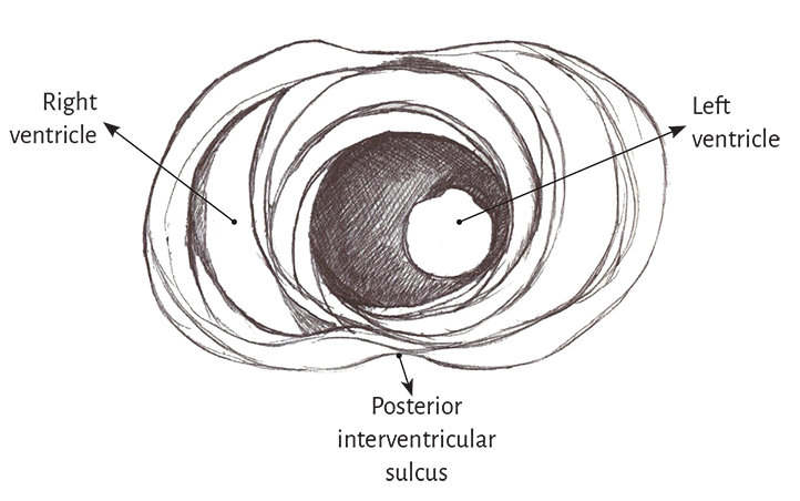
Figure 1.5. Apical view of the left and right ventricles.
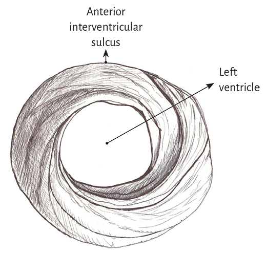
Figure 1.6. Spiral arrangement of apical muscle layers.
In the left ventricular basal half, at the level of its free wall (Figure 1.7), the fibers are arranged similarly to the apical half. A muscle layer with spiral trajectory extends from the surface to the center displaying its fibers from outside to inside (from paraepicardial to paraendocardial regions). At this level their orientation is opposite to that of the apex, following a counter-clockwise trajectory (apical view of the diaphragmatic surface of the heart in anatomical position). This arrangement of the muscle layer in its twist limits a cavity which at the base of the heart is real and not virtual as in the apex.
Figure 1.7. Basal third of the left ventricle.
It depicts the muscle layers of the free wall.
The apex should be considered as a tunnel with a muscular rim surrounding its entire ring, while at the ventricular base this ring has two parts. One part corresponds to the left ventricular free wall and the other to the interventricular septum. In addition, the most superficial basal fibers make contact with the fibrous mitral annulus, a setting that is absent at the apical level. Nevertheless, the essential functional difference between basal and apical regions is their opposite fiber motion. This characteristic determines myocardial torsion to achieve cardiac blood ejection and the untwisting that generates suction and diastolic filling.
Right ventricle. Theoretically, two types of fibers can be identified in its distal half according to their orientation: paraendocardial and paraepicardial fibers. The former extend from the pulmonary base backwards and downwards to the apical region, whereas the others extend from the anterior interventricular sulcus to the back approaching the base of the heart. This X-shaped crossover arrangement allows the fibers in the distal end of the right ventricle to adopt a helical arrangement, turning from subepicardial to subendocardial (Figure 1.8).
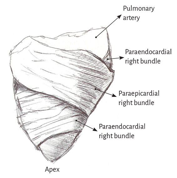
Figure 1.8. Right ventricular free wall.
Three segments can be identified at the basal half of the right ventricle (tricuspid orifice perimeter): free wall, supraventricular crest and interventricular septum. The free wall presents the same general configuration of spiraling fibers that extend from subepicardial to subendocardial positions. Similarly to the left ventricle, there is a difference in the rotating sense of the basal fibers with respect to the distal ones. They follow a counterclockwise trajectory at the basal end and a clockwise trajectory at the distal end (apical view of the diaphragmatic surface of the heart in anatomical position).
The comparison of the rope model (Figure 1.4) with the ventricular apical and basal regions (Figure 1.1) shows the analogy existing between the rope configuration and the myocardial fibers.
3. Segmentation of the myocardial band
In its course, the myocardial band adopts a helical configuration that defines the two ventricular chambers. The myocardial band is characterized by a descending and an ascending band. The former includes the right, left and descending segments, while the latter is formed by the remaining ascending segment (Figure 1.4). The figure in 8 outlined by this trajectory defines two loops: a basal and an apical loop. An interesting article by R. F. Shaner in 1923 (84) expresses that the myocardium is formed by “two flattened muscles arranged into a figure of 8. These muscles shorten in opposite directions in systole, emptying the blood content.”
The myocardial band describes two spiral turns with the insertion of its initial end along the line extending from the pulmonary artery to the orifice of the tricuspid valve, called the pulmo-tricuspid cord, in front of the aorta, while its final end attaches below the aortic root. Both ends are fixed by an osseous, chondroid or tendinous nucleus, depending on the different species (animal or human) used in the studies. This nucleus, which has been termed cardiac fulcrum, is the only perceptible edge where the muscle band fibers originate and end, and will be extensively analyzed in this chapter (Figures 1.16 and 1.19).
The basal loop extends from the base of the pulmonary artery to the central band twist. On the other hand, the apical loop courses from this point of inflexion to the base of the aorta. In turn, each loop consists of two segments. The basal loop consists of the right and left segments and the apical loop of the descending and ascending segments (Figure 1.4). In the general loop configuration, the basal loop envelops the apical loop, so that the right ventricular chamber presents as an open slit in the muscle mass thickness forming both ventricles (Figure 1.1). The segments, in turn, are defined by anatomical structures.
Basal loop. The posterior interventricular sulcus presents a trough that establishes the limit between the right and left segments of the basal loop. The right segment constitutes the right ventricular free wall and surrounds the tricuspid valve orifice on the outside. The left segment situated in the left ventricular free wall defines the mitral valve orifice externally. The fibers run from the subepicardium to the subendocardium following a counterclockwise helical direction (apical view of the diaphragmatic surface of the heart in the anatomical position).
Apical loop. The descending apical segment extends from the twist in the band to the apex, where it becomes the ascending segment to end mainly below the base of the aorta in the cardiac fulcrum, a structure to which the myocardial band fibers attach. Both segments mainly form the interventricular septum. Similarly to the basal loop, the fibers run from the subepicardium to the subendocardium, but in this case following a helical clockwise direction (apical view of the diaphragmatic surface of the heart in the anatomical position).
These concepts indicate that the right ventricular free wall is formed by one loop (basal) and the left ventricular free wall by both loops (basal and apical). The fundamental point for cardiac mechanics is that the base and apical muscle fibers course in different directions. This disparity finds correlation with the fiber trajectories and the helical pattern of the muscle band limiting the ventricles.
4. Anatomy of the cardiac band. Dissection
To dissect the heart it must be boiled in water with acetic acid (15 cc per liter) for approximately two hours and a half, except that a pressure cooker is used, in which case the time is reduced by half. Prior work before unfolding the muscle band consists in separating the atria from the ventricles in a very simple maneuver that demonstrates the different evolutionary origins between both types of chambers. Then, the aorta and the pulmonary artery are cut three centimeters from their origin, separating the attachment between them, and finally, a longitudinal incision is done on the superficial fibers (interband or aberrant fibers) (Figure 1.58) (105, 123, 128) extending transversally along the anterior wall of the ventricles. Prior boiling of the anatomical piece allows the easy execution of all these steps. Between the atrial and the ventricular walls there is only connective tissue, allowing the easy separation of these chambers due to the denaturation produced by heat.
The key maneuver to unfold the myocardial band consists in entering the anterior interventricular sulcus with a blunt instrument, leaving on the left side of the operator the end of the band corresponding to the pulmonary artery and its continuity with the right ventricular free wall (right segment). Next, traction is applied towards the same left side (Figure 1.2), completely releasing the pulmonary artery from the rest of the myocardial band (Figure 1.27). Below the aorta we find the cardiac fulcrum, where the origin and end of the band attach (Figures 1.9 and 1.10). (128)
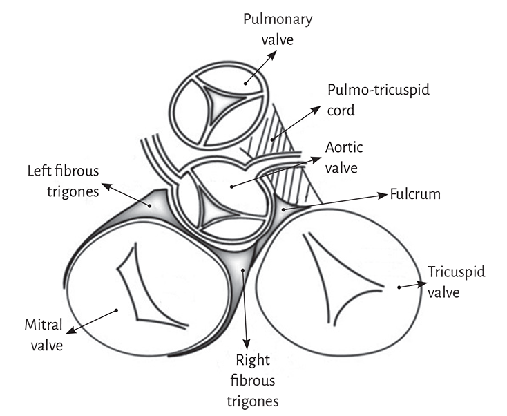
Figure 1.9. Cardiac fulcrum. Septal part of the aortic annulus between the right and left trigones.
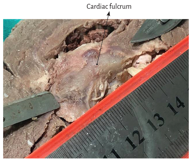
Figure 1.10. Cardiac fulcrum in the bovine heart.
It should be understood that as the myocardial band is unfolded, separating the pulmonary artery and the pulmo-tricuspid cord (anterior) from the ascending segment (posterior), the vision of the homogeneous anatomical reality is lost. This concurrence of the beginning and end of the muscle band in the cardiac fulcrum constitutes a meeting point between the right segment and the ascending segment, origin and end of the myocardial band. Thus, both band ends are situated in the same point, with the origin placed anteriorly to the end of the band. Once the initial end of the band is separated from this meeting point, of great stiffness and certain resistance to the maneuver, the heart loses its functional anatomy (Figures 1.3, 1.11 and 1.27).
The progression of the myocardial band dissection implies finding the whole extent of the right segment, the beginning of the left segment and, at the posterior margin of the right ventricular chamber, the dihedral angle formed by the interventricular septum and the right ventricular free wall (right segment).
The next step (the most delicate one) consists in entering the dihedral angle between the right ventricular and intraseptal fibers. This separation from the right ventricle allows entering a cleavage between the anterior septal band and the intraseptal band (final segment of the myocardial muscle band), at the ventral part of the septum (Figure 1.11 C). Then, the dorsal part of the septum is dissected between the posterior septal band and the left descending segment to remove and separate the aorta.
Finally, the trajectories of the muscle planes belonging to the descending segment are separated in blunt fashion from those of the ascending segment leading to the cardiac fulcrum, contiguously with the aorta at the opposite end of the muscle band, to the right of the operator, allowing the band to be unfolded in all its length (Figure 1.11 D). Figures 1.11 and 1.12 show the sequence of myocardial unfolding until it becomes a muscle band. Being able to unfold the myocardium with a similar thickness in all its extension proves that the band is real and not a “heuristic” construction.
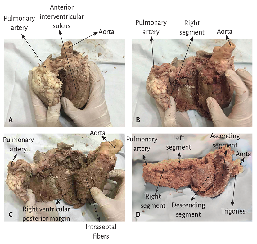
Figure 1.11. Unfolding of the myocardial band.
The diagram in Figure 1.13 details the different segments comprising the band, as well as the final insertions constituting the origin and end of the band, very close to each other in the intact heart.
Histological analysis of the myocardial band. The histological analysis sequence of the unfolded myocardial band demonstrates its linear orientation according to the segmental continuity of its spatial organization when the band is coiled, both in its internal and external surfaces (Figure 1.14). These orientations are identical in both surfaces (internal and external). And if two things are identical it means that they present a unique orientation.
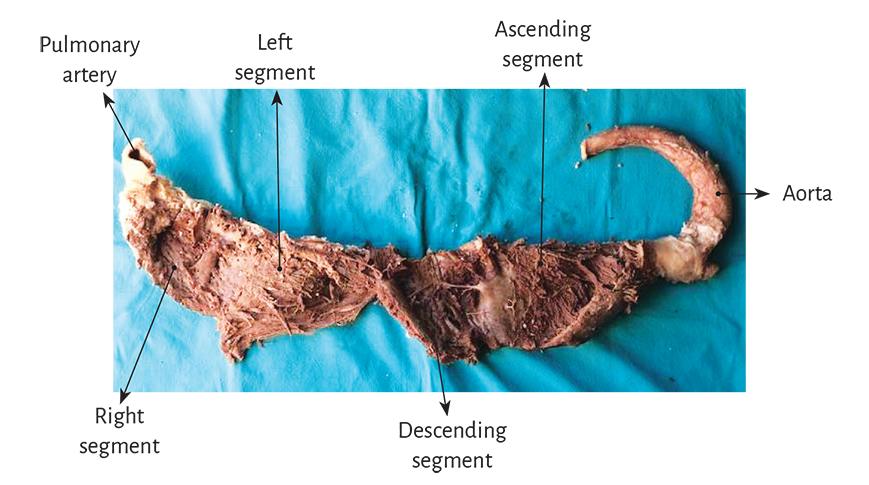
Figure 1.12. Myocardial band unfolded in all its extension.
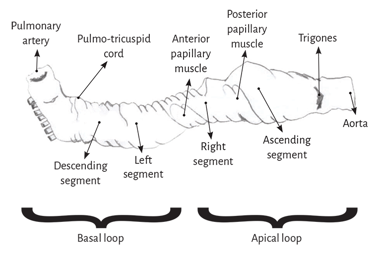
Figure 1.13. Descriptive diagram of the muscle band segments.
It can be seen that the myocardial structure is not a lattice but a band. The lattice concept used was developed due to the band folding resulting in overlapping segments, which are functionally independent and with friction between their surfaces. The sliding motion between segments implies that they have a lubricating system that facilitates autonomous motion with lower energy expenditure despite being overlapped, as will be analyzed in this chapter. This arrangement is essential to achieve myocardial torsion, a fundamental action of cardiac mechanics that would be impossible with the lattice structure (crisscross of myocardial fibers).
No segment of the band histological sequence explored in our investigations presents a lattice organization. As the external surface of the distal descending segment (Figure 1.14, lower panel) twists to become the ascending segment, the cardiomyocytes generate in the planimetric histological sections a different architecture in their orientation from that of the internal surface, only site (cardiac apex) where this situations occurs. The rest of the orientation is always parallel. In the apex, the spiral course of the myocardial fibers, which shift from the periphery towards the center, determine a torsion where the subepicardial fibers become subendocardial, overlapping like the tiles of a roof, as evidenced in this image.
5. Interpretation of the origin and end of the muscle band.
The cardiac fulcrum
As previously expressed, the opposite orientation and rotational movement of the left ventricular fibers, both at the basal and distal apical segment levels, explain Torrent Guasp’s myocardial band model. The author considered that the ventricular myocardium is formed by an assembly of muscle fibers coiled unto themselves as a rope (rope theory) (Figure 1.4) and flattened laterally to form a band, which by giving two spiral turns describes a helix limiting the two ventricles and defining their function. In turn, the phylogenetic study allows to theoretically understand, through the 600 million-year evolution of the circulatory system, that the ends of the band are located at the root of the great vessels, as it is formed from a loop of the primitive circulatory duct. (109)
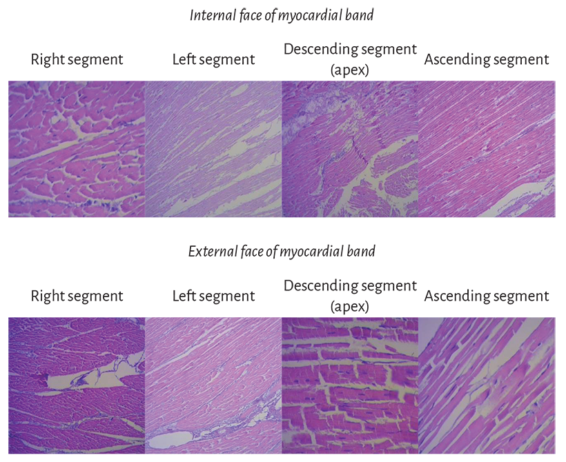
Figure 1.14. Segment sequence from the myocardial band histological analysis.
The muscle shaping the right ventricle corresponds to the origin of the myocardial band (right segment), which begins both in the cardiac fulcrum as in the fibrous structures related with the pulmonary artery and the tricuspid annulus (pulmo-tricuspid cord) (Figures 1.15 to 1.17). The ascending segment, which is part of the autochthonous muscle bundles constituting the left ventricle, ends at the base of the aorta, and the cardiac fulcrum constitutes a solid point of attachment of the end of the myocardial band.
Figure 1.9 demonstrates that the aortic annulus is not continuous. Its circumference is interrupted between the ends of the trigones, in the region where the mitral valve anterior cusp is inserted. Our research has demonstrated that in the course of the aortic annulus septal segment, extending from the left to the right trigone, there is a thickening we have called cardiac fulcrum (below and in front of the right trigone) where most of the myocardial band is attached, since as any muscle needs a supporting point to develop the leverage required to fulfill its function.
The insertion of the myocardial fibers in the fibrous skeleton of the heart has been considered for three centuries. The development of the myocardial band reported in 1970 by Torrent Guasp (106-108) indicates in the anatomical research that it originates and ends at the root of the great vessels, but that the fibers do not insert in the atrioventricular annuli. The myocardium attaches to these annuli but does not insert in them. In our investigations we have not found insertion of cardiomyociytes in the collagen matrix of the trigones (Figure 1.39).
However, Torrent Guasp considered that the myocardial band lacked a fixed supporting point as those present in the muscular system to develop force. In this sense, he assumed that it behaved as the circular muscle of the arteries, finding support in its own chamber blood content (hemoskeleton). In our research, we have always considered that the myocardial band should have a fixed point of attachment to allow its helical rotation in order to achieve its motions and the essential muscle force of shortening-twisting and lengthening-untwisting. The study of a supporting point in the myocardial band finds correlation with an organic engine, such as the heart, which without a firm attachment to a resistant nucleus would lack the necessary mechanical faculties for its considerable power.
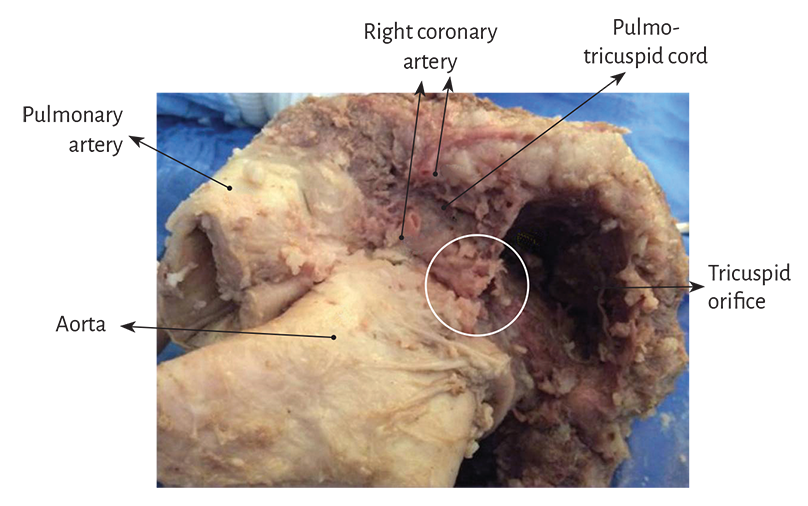
Figure 1.15. Detail of the pulmo-tricuspid cord between the tricuspid orifice and the pulmonary artery where the myocardial band begins. The circle shows the site of the cardiac fulcrum, which is visualized when the pulmonary artery and the pulmo-tricuspid cord are removed from their insertion at the beginning of the myocardial band unfolding (observe figure 1.27). The right coronary artery has been cut to reveal the cord trajectory (bovine heart).
This point of attachment implies, as in any muscle, its ability to achieve the necessary leverage and also to act as a bearing or pad, preventing the force of ventricular rotation, either by torque or torsion strain from transferring to the aorta, thus dissipating the energy produced by the helical muscle motion, and avoiding aortic constriction or bending during systolic ejection. (134)
Young bovine and human hearts (from spontaneous abortion fetuses, explanted adult hearts and cadaveric hearts retrieved from the morgue) were used to study the myocardial band insertion. The dissection was performed as described in Section 4: “Anatomy of the cardiac band. Dissection”, of this same chapter.
In anatomical investigations we have found in all the bovine and human hearts studied a nucleus underlying the right trigone, whose osseus, chondroid or tendinous histological structure depends on the specimen analyzed, and is oriented towards the muscle fibers of the ascending segment which intimately penetrate its structure to attach themselves. This point of attachment would serve to support both the origin and end of the myocardial band, as the fibers that initiate the right segment, origin of the myocardial band, attach to the anterior part of this nucleus as well as to the pulmo-tricuspid cord (Figure 1.16).
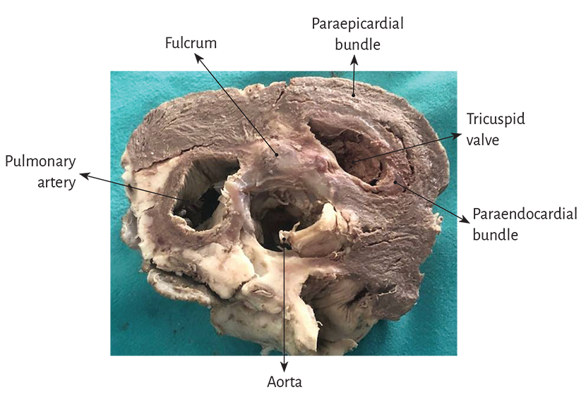
Figure 1.16. Descriptive photograph of the muscle bundles emerging from the cardiac fulcrum, which belong to the right segment forming the right ventricle (transverse section of a bovine heart).
This osseus, chondroid or tendinous attachment point is found in the vicinity of the tricuspid valve (right), the aorta (posterior) and the pulmo-tricuspid cord (anterior) (Figure 1.20). To find it, it is necessary to unfold the myocardial band and move the pulmonary artery, the pulmo-tricuspid cord and the right segment to the left of the observer, stripping the root of the aorta (as a scarf that separates from the neck). Next, the muscular plane of the descending segment is separated from that of the ascending segment to follow the latter up to its insertion in the cardiac fulcrum. This maneuver reveals the fulcrum in front of the aorta and below the right trigone and the origin of the right coronary artery (Figures 1.18 and 1.19), detached from the aortic continuity and inserted as a complementary element between the aorta and the myocardium. This structure, origin and end of the myocardial band, has a more rigid consistency than the trajectory between the trigones.
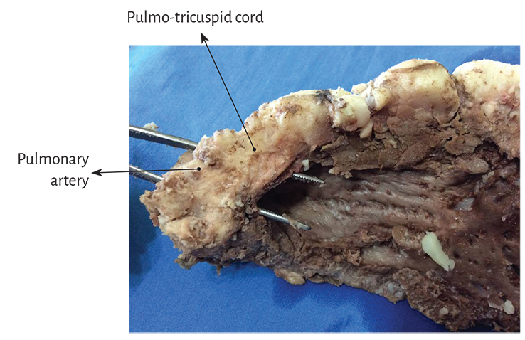
Figure 1.17. Panoramic view of the pulmo-tricuspid cord.
An osseus formation, called os cordis, in bovine and sheep hearts, is reported in the veterinary literature in the same location where we have studied this structure both in bovids and humans. (69, 134) Beyond its mere mention in bovids, no reason for its presence or function was ever assigned to this structure, and it has not been described in humans. In bovids, its consistency is osseus at palpation, which has been confirmed by histological studies, and its size, according to our studies, is of approximately 45 mm × 15 mm, being its triangular shape (Figure 1.20).