


Полная версия
Thermoelectric Microgenerators. Optimization for energy harvesting
Heat flow density
At given efficiency the total converted power will be determined by heat flow Qc passing through the generator module. And it is set by the capacity of the heat source and the heat transport “capacity” (inverse of thermal resistance) of the generator itself. These characteristics must be coordinated.
For coordination it is useful to operate with value of heat flow density on unit of the heat giving surface and heat flow density which is passed by unit of generator surface.
Heat flow density (2.26) is given by the formula:
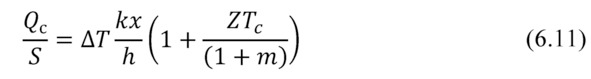
where x – packing density of pellets in TE generator module; k – thermal conductivity of the thermoelements (pellet) thermoelectric material.
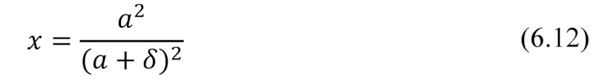
where δ – distance between thermoelements, a – cross-section of the thermoelement.
For practical estimates the data for heat flow density for various types of generator micromodules are provided in Table 6.4.
Thus, at the given temperature difference and the given characteristic of heat conductivity of material of the generator module, heat flow density depends on density of packing of thermoelements in the module design (6.11). The more densely they are packed (less gap between thermoelements), the generator is more powerful.
Density of heat flow passing through the generator characterizes its specific power. This specific characteristic allows calculating of absolute values of a heat flow through the chosen generator module.
Comparison of heat flow density of the heat giving surface and density of a heat flow via the generator gives the answer to a question whether it is necessary in a design of the generator device the big surface of heat collecting. I.e. whether it is necessary to collect and concentrate heat on the generator for his effective work.
Table 6.2. The density of heat flow through different types of generator micromodules at various temperature differences.
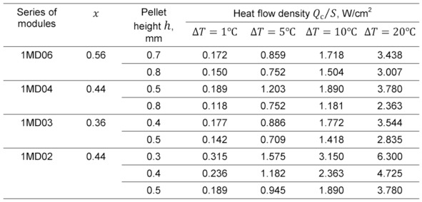
From Table 6.2 it is seen that heat flow density via the generator micromodule can reach several units of W/cm2. To provide such power densities may require heat flow concentrators from heat source (case of low power heat source).
This is important issue for energy harvesting tasks, where low-power heat sources usually have very small values of heat flow power density.
Illustrative example – recycling of the human body heat. Heat flow density of such kind of heat “source” is small compared with tabular values for the microgenerators (Table 6.2) – no more than 10—1…10—2 W/cm2. Clearly, the generator device in such tasks should include heat flow concentrators. Moreover, the area of such a hub should significantly exceed size of the generator micromodule.
Another example is soil generators which utilize heat flowing in the upper layers of soil in the daily cycle. Here the heat flows have values at the level of 100W/m2 (0.01W/cm2). It also requires the concentration of heat for the supply to generator micromodule.
Another important task is to effectively dissipate heat passed through the generator. If this is not achieved, the useful heat, transported through generator system, limited to a size not more than wasted on a radiator.
Here it is also important to the specific characteristics of the density of heat flow through the radiator -" flow capacity” of the radiator. It is necessary to calculate the dimensions of the radiator (see Chapter 9). In many practical cases, dimensions of a heat sink should be also noticeably larger than the generator micromodule.
Chapter 7. Thermoelectric materials
Summary. In this Chapter properties of the thermoelectric materials applied in microgenerators for energy harvesting are considered. On the working temperature range of these tasks, such generators can be classified as “low-temperature”. Besides in this temperature range the majority of thermoelectric coolers works. Therefore also thermoelectric materials for generator applications are used same, as for thermoelectric cooling – solid-state solutions on the basis of the Bi-Sb-Te.
Typical parameters
As shown above (Chapter 6), thermoelectric material properties of the thermoelements play decisive role in the parameters of efficiency of microgenerator modules.
Therefore, when designing of microgenerator it is necessary to pay great attention to properties of thermoelectric material from which they are should be made.
Application of energy harvesting means heat recycling from heat sources of low power, small temperature difference relating to the environment. Approximately this temperature range can be defined as ~250 … 450K (-25… +180°C).
In this regard an analogy arises to other field of applications of thermoelectricity – thermoelectric cooling. Practical temperature range of thermoelectric cooling is approximately similar stated above.
It explains that for thermoelectric generation in energy harvesting tasks practically the same thermoelectric materials on the basis of solid solutions of Bi-Sb-Te, as successfully can be applied as to thermoelectric cooling. Such thermoelectric semiconductor materials have maximal efficiency in this temperature range.
Key properties of thermoelectric material are combined in expression for its Figure-of-Merit Z.
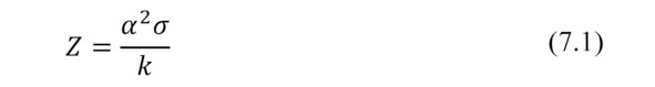
where α – thermoEMF coefficient (Seebeck coefficient) of thermoelectric material; σ – electrical conductivity; k – thermal conductivity.
Typical parameters of thermoelectric material applied for manufacturing of microgenerators and microcoolers are given in Table 7.1.
Table 7.1 Typical parameters of thermoelectric materials of p-and n-types at 300K.

Also temperature dependences of properties in the working temperature ranges are important for detailed calculations and modeling of real devices operation.
For convenience of calculations and mathematical modeling temperature dependences can be presented in the polynomial form.
Temperature dependences of properties of the applied thermoelectric materials are described well by a polynomial of the 3rd order of general view as following
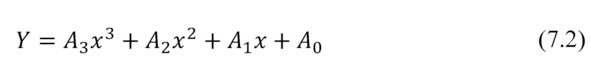
where x=T/100
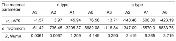
Detailed data for typical polynomial temperature dependences of the major properties are provided in Table 7.2. In Fig. 7.1 these typical temperature dependences are graphically presented.
Table 7.2 Polynomial coefficients of temperature dependences (7.2) of properties of thermoelectric materials.
a)

b)
c)
d)
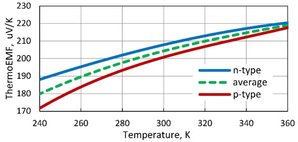
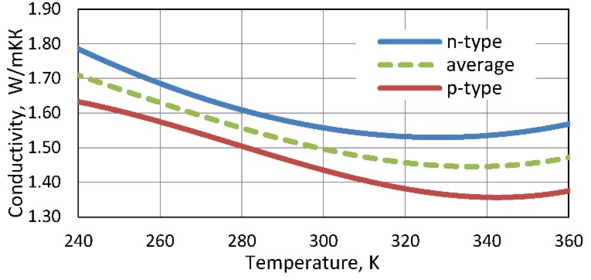
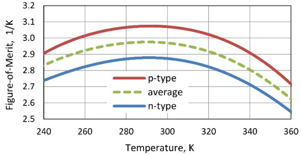
Figure. 7.1 Temperature dependences of thermoelectric materials properties: Seebeck coefficient (a), electric conductivity (b), thermal conductivity (c) and Figure-of-Merit (d).
In calculated parameters of thermoelectric microgenerators average characteristics of pair of thermoelements of n-and p-types are applied. Therefore temperature dependences of properties of materials of both n-and p-types and these average dependences are given in Fig. 7.1. Average dependences characterize properties of p-n pair of such thermoelements. In mathematical formulas for parameters of thermoelectric generators such average properties on p-n to pair of thermoelements are just used.
On the presented temperature dependences it is necessary to make several important remarks.
Voltage
Voltage U provided by generator linearly depends on thermoEMF E, defined by Seebeck coefficient α.
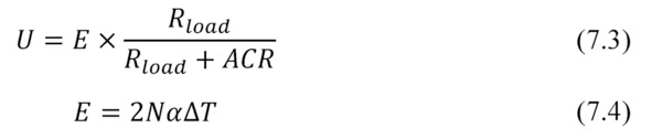
According to temperature dependence α=f (T) (Fig. 7.1a) with increasing of temperature the thermoEMF E, although not significantly, but is growing.
Maximum power
Maximum power of generator can be written as

where N×f – the product of the number N of pairs of thermoelements on the geometrical form-factor f is the specified value.
The factor α2×σ in thermoelectricity is often called as a “power factor”. This factor is significant both for applications in the field of cooling, and in the generator direction. For generators – it shows dependence of the maximum power of Pmax of generator on parameters α and σ of thermoelectric material (7.5).
Since both parameters α and σ have temperature dependencies, with multidirectional (Fig. 7.1a and 7.1b, respectively), to understand the temperature dependence of maximum power Pmax you must be aware of the temperature dependence of α2×σ that is presented in Fig.7.2.
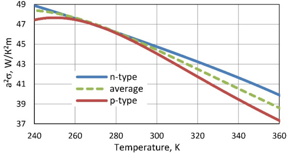
Figure. 7.2 Dependence of α2×σ on temperature.
Follows from this temperature dependence that useful power decreases with growth of temperature.
Coefficient of performance
In the first approximation energy conversion efficiency (4.1) can be expressed as the following

Apparently from a formula (7.6) at the given temperature difference (for example, single ΔT=1℃) efficiency η approximately linearly depends on Figure-of-Merit Z. But this dependence becomes complicated existence of a factor – fractions with Figure-of-Merit parameter.
We will consider the modes of the maximum efficiency m≈1.4 and maximum power mode m=1. Simplified formulas for the efficiency for such modes are the following, respectively.

Fractional factors in both formulas (7.7) and (7.8) – Figure-of Merit factors, have temperature dependences, as shown in Fig. 7.3.
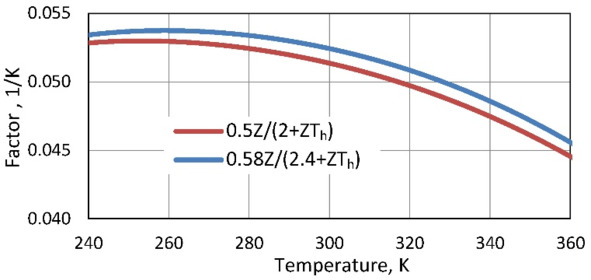
Figure. 7.3 Dependence of Figure-of-Merit on temperature.
The key parameter of material (its Figure-of Merit Z) influencing efficiency has obviously expressed maximum near room temperatures (Fig. 7.1g) – in the range of 280—290K.
Конец ознакомительного фрагмента.
Текст предоставлен ООО «ЛитРес».
Прочитайте эту книгу целиком, купив полную легальную версию на ЛитРес.
Безопасно оплатить книгу можно банковской картой Visa, MasterCard, Maestro, со счета мобильного телефона, с платежного терминала, в салоне МТС или Связной, через PayPal, WebMoney, Яндекс.Деньги, QIWI Кошелек, бонусными картами или другим удобным Вам способом.