


Полная версия
Thermoelectric Microgenerators. Optimization for energy harvesting
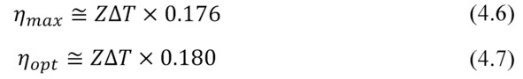
Choosing of practically optimal load resistance between maximum power and maximum efficiency modes can be in the range (Fig. 4.1).
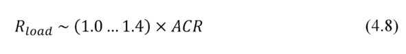
Figure. 4.1 Dependence of the efficiency η and power P related to Pscvs ratio m of resistances for two main generator operation modes – maximuum power (Pmax, mmax, ηmax) and maximum efficiency (Popt, mopt, ηopt).
In practice, use the electric load from this range (4.8) turns out to be more comfortable than to select optimal electric load with exactly the specified value.
From the formula (4.1) with use of (4.3) it can be build a useful table for estimates of the absolute value of the maximum efficiency ηopt of thermoelectric generator depending on temperature difference ΔT (Table 4.1).
Table 4.1 Dependence* of maximum efficiency ηopt vs temperature difference ΔT on a generator.

The common conclusions from formula (4.1) and Table 4.1 are the following:
– in practice, the efficiency ηopt is almost a linear function of the temperature difference ΔT.
– one degree of the temperature difference ΔT gives about 0.05% of maximum efficiency ηopt.
Efficiency and carnot cycle
Useful information on the efficiency of thermoelectric generator should be of the following formulas for two marginal efficiency modes: the maximum efficiency mode ηopt and the maximum power mode ηmax.
For these modes the efficiency η can be written as the following:
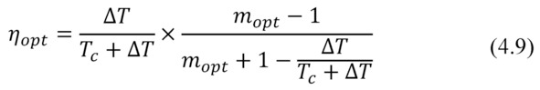
– for maximum efficiency mode ηopt
– for maximum power mode ηmax

In both formulas (4.9) and (4.10) the first fractional multiplier is, generally speaking, the ideal Carnot cycle efficiency (∆T/Th). The second multiplier – thermoelectric factor reduces ideal efficiency of the Carnot cycle.
So, near room temperature (Tc≃ 300K) and typical Z≃0.003K-1 we have an numerical expression for the maximal efficiency ηopt

As for the mode of maximum power efficiency ηmax, correspondingly:
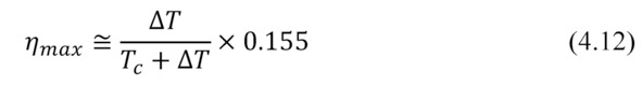
In other words, state-of-art thermoelectric microgenerators provide efficiency only 15.5—16% of the ideal Carnot cycle efficiency.
Here you can make an important note about the maximum possible efficiency for any heat engines used in waste heat recycling applications (energy harvesting).
Namely, the ideal heat engine working by Carnot cycle near room temperature provides efficiency only about 0.33% per degree of temperature difference (4.11).
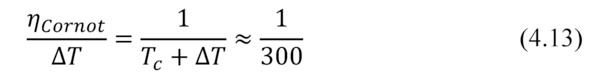
Thus, this is the absolute maximum.
According to Carnot’s theorem, such wording [22]:
“Maximum efficiency of any heat engine may not exceed the efficiency of Carnot heat engine, running at the same temperatures of the heater and cooler.
This is an important point to general understand. To avoid posing unrealistic tasks to retrieve large efficiency with thermoelectric generators – larger than limited by the ideal Carnot cycle.
This issue will be discussed further in Chapter 7.
Chapter 5. Optimization of thermal resistance
Introduction. In this Chapter optimization of use of thermoelectric generator by coordination of thermal resistance of elements of design of the generator device are considered. As it appears, coordination on thermal resistance is in many respects similar to coordination of electric load resistance. Namely, there is an optimal solution with maximum efficiency at a certain ratio of thermal resistance of the generator module and other elements of a design.
Thermal resistance
Working parameters of a thermoelectric generator is determined by temperature difference ∆T that is created when heat is passing through the generator.

In basic formulas for thermoEMF E, efficiency η and net power Pthe working temperature difference ∆T is mentioned that is created directly on the sides (hot and cold) of the generator module.
In practice, however, this working ∆T is less than total temperature difference ∆Ts that is created at generator device by heat source relating to the envirnment, where heat is dissipated (Figure 5.1).
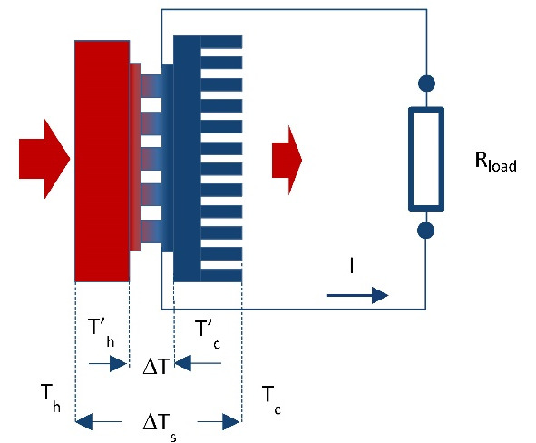
Figure. 5.1 Simplified schema of generator device in working arrangement with interfaces and heat sink.
Total temperature difference:
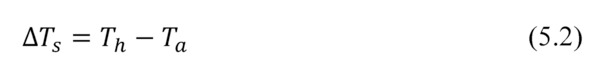
where Th – temperature of heat source; Ta – ambient temperature.
Working (net) temperature difference ∆T on generator module is always less than total value ∆Ts:

This is due to the fact that in the design with thermoelectric generator inevitable parasitic thermal contact resistance at the crossings of the design. Particularly thermal resistance of heat sink is most important, the heat which dissipates into the surrounding ambient (Fig. 5.1).
In general
where Ȓs – total thermal resistance of generator device; Ȓ’TEG – thermal resistance of working thermoelectric generator module; Ȓc -thermal resistances other items of the generator device.
Presence of parasitic thermal resistances Ȓc besides total thermal resistance of generator device Ȓs reduces working temperature difference ∆T on TE generator module in relation to the total difference ∆Ts and, consequently, reduces its effectiveness.
Taking into account formulas (2.24) and (2.25)

where T’C – temperature on cold side of thermoelectric generator; ȒTEG – thermal resistance of thermal conductivity of the thermoelectric generator.
In practical tasks, you must always strive to reduce parasitic heat resistance of construction, because it means a loss of working temperature difference and correspondingly – efficiency of generator.
However, as there is always non-zero values of such losses (Ȓc> 0) it is necessary an approach of optimization – the search for an optimal balance of these values Ȓ’TEG and Ȓc
Net power
Consider net power P converted by thermoelectric generator.
where ACR – internal resistance of thermoelectric generator; m – ratio of resistances: external electrical load to internal resistance of the generator.
Here

where f – thermoelement form-factor (ratio of cross-section to height); p – electrical resistivity of thermoelement material; a -thermoelectric coefficient (Seebeck coefficient) of thermoelectric material of thermoelement; N – number of pairs of thermoelements.
Then
With

where k -thermal conductivity of thermoelement; Z – Figure of Merit.
Then the desired dependency of net power conversion P from the thermal resistance is:
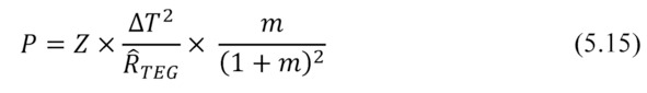
Where given (5.6) and (5.7) the total dependence of net power Pon heat resistance for full temperature difference ∆Ts the system is as follows.

Maximum power
Maximum power Pmax is a particular case of the above general formula (5.16), namely, at m=1. The expression for maximum power Pmax has the following form
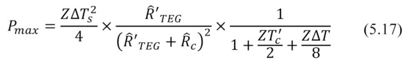
The formula (5.17) and graphical view (Fig. 5.2) for maximum output power Pmax from the thermal resistance Ȓ'TEG of the working generator is similar to the dependence of the power from the electrical resistance (Fig. 3.1). Namely, in both cases there are local maximums of power.

Figure. 5.2 Dependence of power P from thermal resistance of generator module ȒTEG at different thermal resistances of the rest of the system Ȓc (paracitic thermal resistance). Here full temperature difference is ∆Ts=10°C. Dotted line – power at zero parazitic thermal resistance – when the working temperature difference is a half (∆T=5°C).
In the case of thermal resistances optimization – maximum power is achieved with equal thermal resistance of working generator Ȓ'TEGand other (sum of parasitic) thermal resistances Ȓc of the generator system.
Physical sense
Optimizing of thermal resistance has a simple physical meaning.
Generator works optimally if its heat transport capacity (thermal conductivity is inverse value to thermal resistance) and heat throughput of all other structural elements (primarily is the element responsible for heat -dissipation of past heat) agreed upon, namely, equal.
For simplicity we will consider only the element of heat dissipation – heat sink. If its heat transport capacity is less than similar parameter of generator module, less heat passes through the system as a whole the generator converts less efficient.
On the other hand, the smaller thermal resistance of heat sink is better. And generator with the specified thermal resistance works better (example, Figure 5.1 – up arrow). But then already the generator will “brake” heat flow, as its thermal resistance becomes higher than of the heat sink.
For smaller thermal resistance of heat transport, there is a different, more optimal generator that will produce even more power (Figure 5.1 – red arrow sideways). But such more optimal thermal resistance of the generator should be smaller. So according to (5.17) and Fig.5.2 it should correspond to thermal resistance of the heat exchange element (Fig. 5.1 – red down arrow).
Particular solutions
Note that maximum power is achieved when there is no loss in generator on parasitic thermal resistances. This is a particular (ideal) case when the full temperature difference drops on the generator module:

In real system with finite parasitic thermal resistance (then ΔT <ΔTs), the maximal available output power is 4 times (!) less than the maximum power output under ideal conditions.
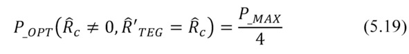
In a case of non-zero parasitic thermal resistance the optimal case is the equality Ȓ’TEG=Ȓc. This is equivalent to the ideal case of half temperature difference on the generator module (ΔT=½ΔTs). The dependence of the power from the temperature difference is quadratic. This explains the ¼ of the optimum output power (5.18—5.19).
The construction of thermoelectric generators allows quite easily manage their thermal resistance. Namely, to obtain the optimal solution for the thermal resistance (thermal resistance change) there is a direct way to change the height and/or cross-sections of thermoelements of generator module.
Heat runs directly in thermoelectric generator through the thermoelements. Their thermal resistance is fundamental in the total thermal resistance of TE generator. Therefore, variation in height and cross section of thermoelements allows optimizing thermal resistance of the TE generator for maximum efficiency.
Thermal resistance of working generator
It must be noted that in the working generator module the effective thermal resistance, namely, the ratio of temperature difference to transported heat power differs from the thermal resistance related to the heat conductivity (Chapter 2). And approach of optimization on thermal resistance needs to be applied to the effective thermal resistance, i.e. taking into account ratios (2.24) – (2.26).
In contrast to thermal resistance of thermal conductivity ȒTEG the effective thermal resistance Ȓ’TEG of working thermoelectric generator depends on the operating mode (2.28).
– When an open electrical circuit the m=∞ and Ȓ’TEG=ȒTEG.
– At maximum efficiency mode the value mopt≈1.4 is given by the expression (4.2). If ZT≈1, the effective thermal resistance Ȓ’TEG turns out to be approximately 29% less then thermal resistance of thermal conductivity ȒTEG.
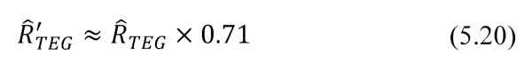
– In maximum power mode m=1 and the effective thermal resistance of approximately a third less than ȒTEG.
Since the heat resistances at maximum power (5.20) and maximum efficiency (5.21) modes differ slightly, it is often convenient to perform all calculations and modeling for maximum power mode with m=1.
Chapter 6. Design optimization
Summary. In this Chapter dependences of parameters of thermoelectric generators on elements of their design are considered. The analysis is provided on the example of the known wide nomenclature range of microgenerator modules. On these examples it is given an idea, what parameters of generators and what role they play in their efficiency and in consumer properties.
Introduction
Useful formulas are illustrated on the example of series of standard TE microgenerators developed earlier [5] in the TEC Microsystems GmbH company in relation to tasks of “low power” – energy harvesting applications.
The nomenclature of thermoelectric modules of TEC Microsystems GmbH is developed with use of classification system of thermoelectric micromodules [6]. This classification allows systematizing thermoelectric micromodules on series in compliance with their parameters and features of a design (see also Chapter 12).
Thus, logical ranks of micromodules convenient for their choice for practical applications are created.
Number of thermoelements
The number of thermoelements 2N in the generator module at the specified temperature difference ∆T and Seebeck coefficient αdetermines the key characteristic – total thermoEMF E.
The value of thermoEMF E provided by the generator determines the output voltage U in the load circuit.

Depending on value of load resistance Rload the working voltageU range of generator could vary widely.
In maximum power mode
If to increase load resistance Rload in the limit we have

Value of thermoEMF E and corerspoindingly output voltage U of generators are variable; depend on the value of temperature drop ∆T. It is not so convenient for consumers of such non-stable power supply – to electronic devices.
Always it is necessary to use electronic DC-DC converter to transform the generator variable voltage to the standard supply voltage of electronic devices.
The DC-DC converters have restrictions on the minimum input voltage which they can transform. It needs to be taken into account. And thermoelectric generators selected for practical applications must be capable to give working voltage not below the minimum threshold of the applied DC-DC converter. In more detail about the choice of a DC-DC converters see Chapter 10.
Zones of applicability of modern DC-DC converters with the minimum input voltage are given in Fig. 6.1. It is, for instance, 20 mV (Linear Technology) [3], 80 mV and 250 mV (Texas Instruments) [4].
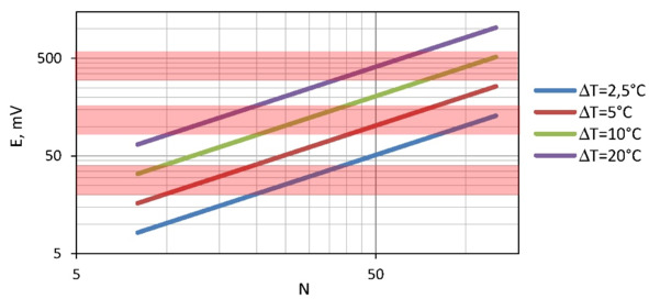
Figure. 6.1 ThermoEMF E depending on the number of pellet pairs N under various temperature differences ΔT.
Besides, low input voltage of the DC-DC converter requires to pay additional “cost”. It is the converter efficiency. The input voltage is lower – the efficiency of transformation of the DC-DC electronic scheme is lower.
In this regard it is more preferable to use generators giving the bigger thermoEMF, i.e. generators with a large number of thermoelements (see Fig. 6.1). Besides, practical tasks sometimes force to leave absolutely optimal solutions for generator. I.e. to use electric loads with a resistance bigger, than ACR, to increase the output voltage of the generator, though by reduction of generator’s efficiency.
It means to consider efficiencies of thermoelectric generator and DC-DC electrical circuit in a combination to obtain maximal output value (see Chapter 10).
Form-factor of thermoelements
The form-factor f of thermoelements of the generator module determines its total electric resistance.
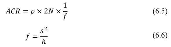
where f – form-factor of a thermoelement.
Here we neglect the additional resistance of the generator module construction (conductors, places of soldering of thermoelements, resistance of barrier layers). In most cases it is valid, as this additional resistance is insignificant usually in comparison of the sum of resistance of thermoelements (6.5).
Then
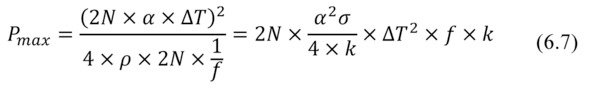
The formula for maximum power Pmax through the generator number of thermoelements N and their form-factor f has a finite shape
Thermal resistance
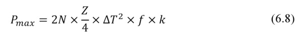
Thermal resistance ȒTEG of thermoelectric generator determines its overall performance.

Formula (6.8) can be converted to a dependence of maximum power Pmax vs thermal resistance ȒTEG of generator.


Figure. 6.2 Power Pmax of generators of different series (developed by TEC Microsystems) vs their thermal resistance ȒTEG at different temperature differences ΔT: Points mark the boundaries of the applicability of these series (1MD02, 1MD03, 1MD04 and 1MD06).
This formula (6.10) and the provided graph (Fig. 6.2) are important for understanding of features of practical applications of generator modules and the choice of optimal solutions.
The power provided by the generator depends on its Figure-of-Merit Z, thermal resistance ȒTEG and temperature difference ∆T.
– Figure-of-Merit Z is defined by properties of the thermoelectric material used in the generator module and a design of the module. For different designs of generators average Figure-of-Merit Z – it a little changeable size is at the level of 2.8…3.0⨯10—3 K-1 (Table 7.1).
– Temperature difference ∆T for a specific case is the value set up by the heat source and the environment.
– The only changeable parameter is the thermal resistance ȒTEG. It can vary widely for a particular design of TE generator just by changing the form-factor – by height and cross-section of thermoelements and number of the thermoelements.
Fig. 6.2 shows the broad range of applicability of modules of given nomenclature. It is due to an opportunity in these series to change form-factor (cross-section and height) of thermoelements and its number.
Coefficient of performance
In accordance with (2.21) the efficiency of the thermoelectric microgenerator in the modes of the maximum power (m=1) or maximum efficiency when mopt~1.4 (4.5) is determined only by the performance of the thermoelectric material – Figure-of-Merit Z, temperature difference on the generator module ∆T and averaged working temperature (Th+Tc) /2.
For practical estimates the efficiency values at averaged temperature 320K and typical values of Figure-of-Merit Z (Chapter 7, Table 7.1) of generator micromodules are given in Table 6.1.
Table 6.1 Efficiency of generator modules depending on temperature difference (at average temperature 320K).
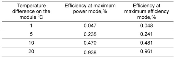
For the small temperature differences it is possible with good precision to consider that every degree of temperature difference provides: in the mode of the maximum power the efficiency ~ 0.047%, and in the mode of the maximum efficiency ~ 0.048% of the efficiency.
It should be noted, at increasing of average temperature the efficiency falls down (see Chapter 7). For example, in Chapter 4 it has been shown that at average temperature 300K by one degree of temperature difference the efficiency is about 0.05% (Table 4.1).
From Table 6.1 it follows that at a temperature slightly above (320K) – efficiency per one degree is slightly lower (~ 0.047%). It is explained by temperature dependences of thermoelectric material of the generators (Chapter 7, Fig. 7.3).