 полная версия
Handwork in Wood
Then all at once down by the face something crashed, the entire stream became alive. It hissed and roared, it shrieked, groaned, and grumbled. At first slowly, then more rapidly, the very fore-front of the center melted inward and forward and downward, until it caught the fierce rush of the freshet and shot out from under the jam. Far up-stream, bristling and formidable, the tons of logs, grinding savagely together, swept forward. * * *
Then in a manner wonderful to behold, thru the smother of foam and spray, thru the crash and yell of timbers, protesting the flood's hurrying, thru the leap of destruction, the drivers zigzagged calmly and surely to the shore.
Sometimes cables have to be stretched across the chasm, and special rigging devised to let the men down to their dangerous task and more especially to save them from danger when the crash comes.

Fig. 20. Splash-Dam.
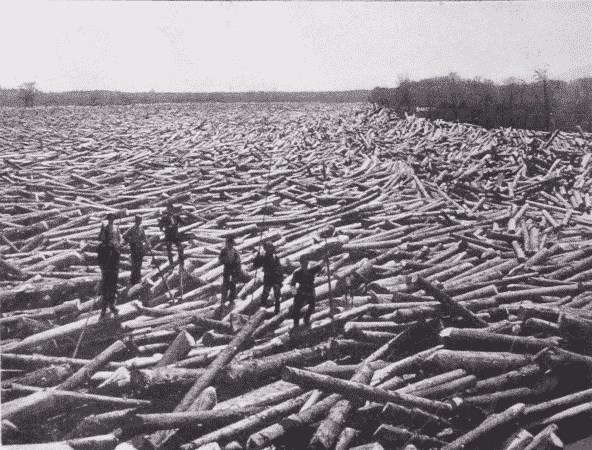
Fig. 21. Logs in Boom. Glens Falls, New York.
In case such efforts are unavailing, it is necessary to "shoot" the jam with dynamite. Another device resorted to where the supply of water is insufficient is the splash-dam, Fig. 20. The object is to make the operator independent of freshets, by accumulating a head of water and then, by lifting the gates, creating an artificial freshet, sufficient to float the timber down stream.
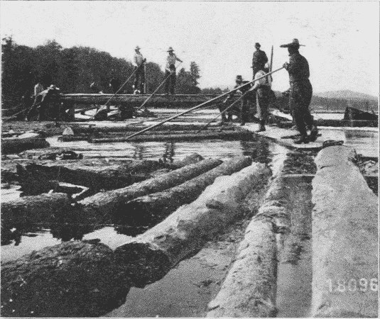
Fig. 22. A Sorting Jack.
Thus by one means and another, the logs are driven along until caught by a boom, Fig. 21, which consists of a chain of logs stretched across the river, usually at a mill. Since the river is a common carrier, the drives of a number of logging companies may float into the mill pond together. But each log is stamped on both ends, so that it can be sorted out, Fig. 22, and sent into the boom of its owner.
MECHANICAL METHODS IN LUMBERINGThe operations described above are those common in the lumber regions of the northeast and the Lake States. But special conditions produce special methods. A very effective device where streams are small is the flume, Fig. 23. This is a long wooden trough thru which water is led, and the logs floated end on. It is sometimes many miles long; in one case in California twenty-five miles.
In the South where there is no snow, logs are largely brought out to the railway or river by being hung under immense two-wheeled trucks, called slip-tongue carts, drawn by mules, Fig. 24. The wheels are nearly eight feet in diameter.
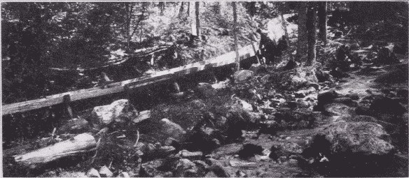
Fig. 23. Six Mile Flume. Adirondack Mountains, New York.
Some kinds of wood are so heavy that they will not float at all, and some sink so readily that it does not pay to transport them by river. In such cases temporary railways are usually resorted to.
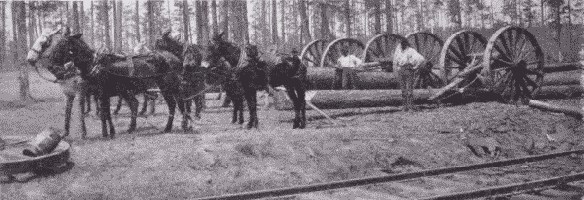
Fig. 24. Hauling Logs by Mules. Oscilla, Georgia.
On the Pacific coast, where the forests are dense, the trees of enormous size, and no ice road is possible, still other special methods have been devised. On so great a scale are the operations conducted that they may properly be called engineering feats. Consider for a moment the size of the trees: red fir ranges from five to fifteen feet in diameter, is commonly two hundred fifty feet high, and sometimes three hundred twenty-five feet high. The logs are commonly cut twenty-five feet long, and such logs often weigh thirty to forty tons each, and the logs of a single tree may weigh together one hundred fifty tons. The logging of such trees requires special appliances. Until recently all the improved methods were in forms of transportation, the felling still being done by hand with very long saws, Fig. 25, but now even the felling and sawing of logs in the forest is partly done by machinery.
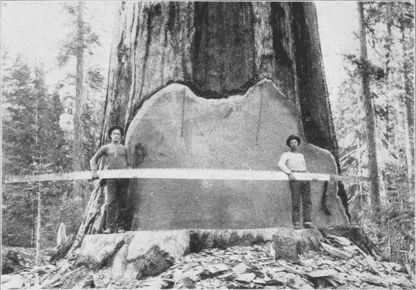
Fig. 25. A Twenty-Five Foot Saw used for Crosscutting Big Logs.
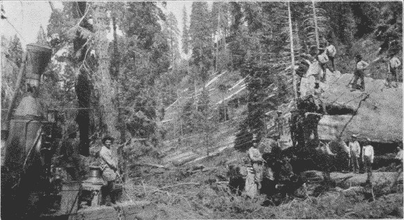
Fig. 26. Hauling Big Logs by Donkey Engine.
To work the saw, power is supplied by a steam or gasoline engine mounted upon a truck which can be taken readily from place to place. As the maximum power required is not over ten-horse-power, the apparatus is so light that it can be moved about easily. The saw can be adjusted to cut horizontally, vertically, or obliquely, and hence is used for sawing into lengths as well as for felling.
Falling beds. Since the weight of a two hundred fifty foot fir is such that if the impact of its fall be not gradually checked the force with which it strikes the ground may split the trunk, a bed for its fall is prepared by the swampers. Usually piles of brush are placed as buffers along the "falling line" so that the trunk will strike these. If the tree stands on the hill side, it is thrown up hill, in order to shorten the fall.
After the felling comes the trimming of branches and knots and "rossing" of bark, to lessen the friction in sliding along the skidway.
The skidway. By the skidway in the Puget Sound region is meant a corduroy road. This is constructed of trunks of trees ranging from a foot to two feet in diameter. These are "rossed," that is, stripped of their bark and laid across the road, where they are held in place by pegs driven into the ground, and by strips spiked upon the tops of the logs. If possible they are laid in swampy places to keep the surface damp and slippery. At turns in the road, pulleys are hung, thru which the hauling cables pass. The skidway runs to the railway siding or water's edge. Over these skidways the logs are hauled out by various means. Formerly "strings" of oxen or Percheron horses were used, but they are now largely superseded by some form of donkey engine, Fig. 26. These are placed at the center of a "yard."
Yarding is the skidding of logs to the railway or water way by means of these donkey engines. Attached to the donkey engine are two drums, one for the direct cable, three-fourths to one inch in diameter and often half a mile long, to haul in the logs, the other for the smaller return cable, twice as long as the direct cable and used to haul back the direct cable. At the upper end of the skidway, when the logs are ready to be taken to the railway or boomed, they are fastened together, end to end, in "turns" of four or more. The direct cable is attached to the front of the "turn", and the return cable to the rear end. By winding the direct cable on its drum, the "turn" is hauled in. The return cable is used to haul back the end of the direct cable, and also, in case of a jam, to pull back and straighten out the turn. Instead of a return cable a horse is often used to haul out the direct cable. Signaling from the upper end of the skidway to the engineer is done by a wire connected to the donkey's whistle, by an electric bell, or by telephone.
Sometimes these donkey engines are in relays, one engine hauling a turn of logs to within reach of the next one, which passes it on to the next until the siding is reached.
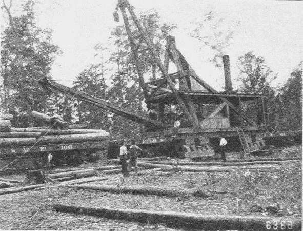
Fig. 27. Steam Skidder at Work. Grant County, Arkansas.
Where there are steep canons to be crossed, a wire trolley may be stretched and the great logs carried over suspended from it.
In the South a complicated machine called a steam skidder, Fig. 27, equipped with drums, booms, etc., is much used both for skidding in the logs and then for loading them on the cars. It is itself mounted on a flat car.
An improvement on this is the locomotive boom derrick which is widely used both on the Pacific coast and of late in the Lake Superior region. It is a combined locomotive, skidder and loader. Its most unique feature is that it can be lifted off the track so as to allow flat cars to run underneath it. This feat is accomplished thus: A device, which is something like that used in elevating the bodies of coal wagons, lifts the engine several feet above the rails. Then steel legs, which are curved outwardly, are lowered until the shoes which are attached to them rest on the outward end of the railroad ties. The truck of the locomotive is then folded up under it out of the way and cars can run under it, the curved legs giving plenty of clearance. The derrick attached is of the breast type, the two legs being firmly fastened. When anchored the engine can be used either for skidding or loading. For skidding, there are two cables, one being run out while the other is being wound on its drum.
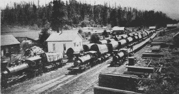
Fig. 28. Log Train, Humboldt County, California.
In loading, the machine is located so that the empty car will be directly in front of it, and then the logs are lifted up and placed on the car by the derrick. When the car is loaded the machine can either move on to the next car, or pull it under itself into place. With the help of four men it can load from 125,000 to 150,000 feet of timber in a day. By means of the cable it can make up a train, and then by lowering the truck and raising the legs out of the way, it is converted into a locomotive and hauls the train away to the mill or railway station at the rate of three or four miles at hour.
As forests are cut away along the water courses, railways have to be resorted to more and more, Fig. 28. This has had a stimulative effect on the logging business, for now the logger is independent of the snow. On account of the steep grades and sharp curves often necessary in logging railways, a geared locomotive is sometimes used, Fig. 29. It can haul a train of twenty loaded cars up a twelve per cent grade. The geared engine has also been used as a substitute for cable power, in "yarding" operations. The "turns" of logs are drawn over the ground between the rails, being fastened to the rear of the engine by hook and cable. This has proved to be a very economical use of power and plant.

Fig. 29. Donkey Engine Yarding.
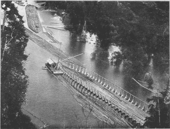
Fig. 30. Giant Raft. In the background is a completed raft;
in the foreground a cradle in which a raft is being built.
Another method of traction where the woodland is open enough is with a traction engine. The ones employed have sixty to one hundred horse power. The great logs may be placed on wood rollers, as a house is when moved, or the logs may be hauled in on a low truck with broad wheels. The "tractor" hauls the log direct to the railway if the distance is not too great.

Fig. 31. Snow Locomotive. Takes the place of 12 teamsters and 12 horses. Minnesota.
In Northern Michigan a "snow locomotive," Fig. 31, is coming into use, which has tremendous tractive power, hauling one hundred to one hundred fifty tons of lumber over snow or ice. It moves on runners, but there is between them a large cylinder armed with teeth. This cylinder can be raised or lowered by the operator as it moves over the surface of the ground. The teeth catch in the snow or ice, and since the cylinder is heated by the exhaust steam, it melts and packs the snow for the trucks following it. The drum is six feet in diameter, with walls an inch and a half thick, and it weighs seven tons. It is used in all sorts of places where horses cannot go, as in swamps, and by substituting wheels for runners it has even been used on sand.
In the Canadian lakes there has been devised a queer creature called an "alligator," a small and heavily equipped vessel for hauling the logs thru the lakes. When its operations in one lake are finished, a wire cable is taken ashore and made fast to some tree or other safe anchorage, the capstan on its forward deck is revolved by steam and the "alligator" hauls itself out of the water across lots to the next lake and begins work there.
The greatest improvement in water transportation is the giant raft, Fig. 30. When such a raft is made up, logs of uniform length are placed together, the width of the raft being from sixty to one hundred feet and its length, one thousand feet or more. It may contain a million board feet of timber. The different sections are placed end to end, and long boom sticks, i. e., logs sixty to seventy feet long, are placed around them to bind the different sections together, and finally the whole mass is heavily chained. Such a raft has been towed across the Pacific.
LOGGINGReferences2
River Lumbering.
Pinchot, Primer, II, pp. 40-53.
White, Blazed Trail, pp. 5-15, 25, 38-39, 52-53, 63-65, 72-85, 91-99, 113-125, 134, 181-196, 216-229, 257, 268, 320-343, 355, 365 ff.
For. Bull., No. 34, pp. 33-41, Fox.
White, Jun. Mun., 10: 362.
Hulbert, Outl., 76; 801.
Wood Craft, 4: 55.
Smith, K., World's Work, 7: 4435.
Mechanical Methods.
World's Work, 7: 4435.
Outl., 76: 812.
Bruncken, p. 86.
Bruncken, pp. 76-87.
Munn, Cosmop., 37: 441.
Roth, First Book, pp. 133-174.
Hovey-King, Rev. of Rev., 27: 317.
Jones, Cosmop., 15: 63.
Price, World's Work, 5: 3207.
For. Bull., No. 61.
Cassier, 29: 443, April, '06.
Cosmop., 37: 445.
Rev. of Rev., 28: 319.
Chapter II.
SAWMILLING
The principal saws in a mill are of three kinds, the circular, Fig. 32, the gang, Fig. 33, and the band, Fig. 34. The circular-saw, tho very rapid, is the most wasteful because of the wide kerf, and of course the larger the saw the thicker it is and the wider the kerf. The waste in sawdust is about one-fifth of the log. In order to lessen this amount two smaller saws, one hung directly above the other, have been used. One saws the lower half of the log and the other the upper half. In this way, it is possible to cut very large logs with the circular-saw and with less waste. The circular-saw is not a perfectly flat disc, but when at rest is slightly convex on one side and concave on the other. This fullness can be pushed back and forth as can the bottom of an oil-can. When moving at a high rate of speed, however, the saw flattens itself by centrifugal force. This enables it to cut straight with great accuracy.
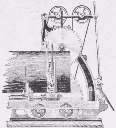
Fig. 32. Double Circular-Saw and Carriage.
A gang-saw is simply a series of straight saw-blades set in a vertical frame. This has a reciprocating motion, enabling it to cut a log into a number of boards at one time. It has this drawback, that it must cut the size of lumber for which it is set; that is, the sawyer has no choice in cutting the thickness, but it is very economical, wasting only one-eighth of the log in sawdust. A special form is the flooring gang. It consists of a number of saws placed one inch apart. Thick planks are run thru it to saw up flooring.

Fig. 33. Gang-Saw.
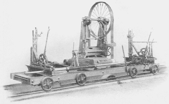
Fig. 34. Band-Saw.
The band-saw is fast displacing the other two, wherever it can be used. It cuts with great rapidity and the kerf is narrow. When first used it could not be depended upon to cut straight, but by utilizing the same principle that is used in the circular-saw, of putting the cutting edge under great tension by making it slightly shorter than the middle of the saw, it now cuts with great accuracy. Band-saws are now made up to 12 inches wide, 50 feet long, and run at the rate of 10,000 feet a minute. They are even made with the cutting teeth on both edges, so that the log can be sawed both going and coming. This idea was unsuccessful until the invention of the telescopic band-mill, Fig. 35. In this the entire mechanism carrying the wheels on which the band-saw revolves can be moved up and down, so as to bring the point where the saw leaves the upper wheel as close to the top of the different sized logs as possible.
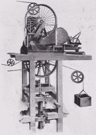
Fig. 35. Double-Carrying Telescopic Band-Mill.
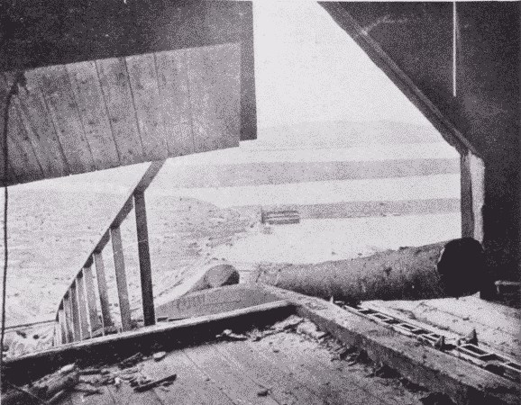
Fig. 36. Jack-Ladder, with Endless Chain. Mill in raised position for large log.
The usual modern mill is a two story building, Fig. 37, built at a convenient locality both for receiving the logs and for shipping the lumber. Whether the logs arrive by water or by rail, they are, if possible, stored in a mill-pond until used in order to prevent checking, discoloration, decay, and worm attack. From the pond they are hauled up out of the water on to a "jack-ladder," by means of an endless chain, provided with saddles or spurs which engage the logs and draw them up into the second story on to the log slip, Fig. 36.
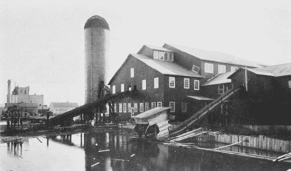
Fig. 37. Two-Story Mill at Virginia, Minnesota, Showing Jack-Ladders and Consumer.

Fig. 38. Log-Flipper.
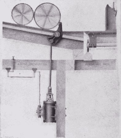
Fig. 39. Log-Stop and Loader. By letting steam into the cylinder, the projecting arm revolves, rolling one log over onto the carriage and holding the next one till wanted.
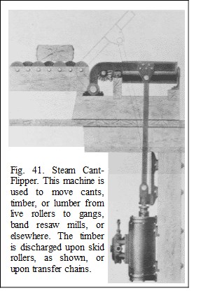
After the logs have entered the mill, they are inspected for stones lodged in the bark, and for spikes left by the river men, and then measured. Under the log-slip is the steam "flipper" or "kicker," Fig. 38, by means of which the scaler or his assistant, throwing a lever, causes the log to be kicked over to one side or the other, on to the log-deck, an inclined floor sloping toward the saw-carriage. Down this the log rolls until stopped by a log-stop, or log-loader, Fig. 39, a double-aimed projection, which prevents it from rolling on the carriage till wanted. This stop is also worked by steam. By letting the steam into the cylinder which controls it, one log is rolled over on the carriage and the next one held. The log on the carriage is at once "dogged," that is, clamped tight by iron dogs, the carriage is set for the proper cut, and moves forward to the saw which cuts off the first slab. The carriage is then "gigged" or reversed. This operation offsets the carriage one-eighth of an inch so that the log returns entirely clear of the saw. In the same way two or three 1" boards are taken off, the dogs are then knocked out, and the log canted over half a revolution. This is done by means of the "steam nigger," Fig. 40, a long, perpendicular toothed bar which comes up thru the floor, engages the log, and turns it over till the sawn side comes up against the knees of the carriage. The log is dogged again and a second slab and several boards are taken off. The log or "stock" as it is now called, is 10", 12", 14", or 16" thick; the "nigger" then gives it a quarter-turn, leaving it lying on a sawn side. It is dogged again, and all sawn up except enough to make a few boards. This last piece is given a half-turn, bringing the sawn side against the knees, and it is sawn up. Each board as it is sawn off is thrown by the board-flipper or cant-flipper,3 Fig. 41, on to the "live rollers," which take it to the next process. Another log comes on the carriage and the process is repeated.
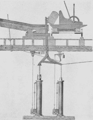
Fig. 40. The Steam Nigger.
The toothed bar turns the log over into the desired position.
The saw-carriage, Fig. 42, is propelled forward and back by a piston running in a long cylinder, into either end of which steam can be turned by the operator.
As the sawn boards fall off the log, they land on "live," that is, revolving rollers, which carry them along at the rate of 200 to 250 feet a minute. Stops are provided farther along to stop the boards wherever wanted, as at the edger, Fig. 43, or the slasher. From the live rollers the boards are transferred automatically, Fig. 44, by chains running at right angles to the rollers and brought within reach of the edger man. About one-third of the boards of a log have rough edges, and are called "waney." These must go thru the edger to make their edges parallel. The edger man works with great speed. He sees at once what can be made out of a board, places it in position and runs it thru. From the edger the boards are carried to the trimmer, which cuts the length. The lumberman's rule is to "cut so that you can cut again." The so-called 16' logs are really 16' 6". The trimmer, Fig. 45, now trims these boards to 16' 1", so that if desired they can still be cut again. The trimmer may be set to cut at any desired length according to the specifications.
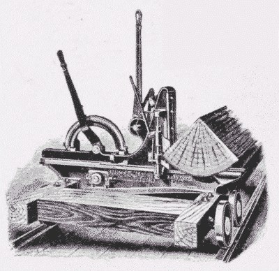
Fig. 42. Log-Carriage, holding quartered log in position to saw.

Fig. 43. Double Gang Edger. This machine trims off the rough edges of the "waney" boards by means of the four saws in the main frame of the machine.
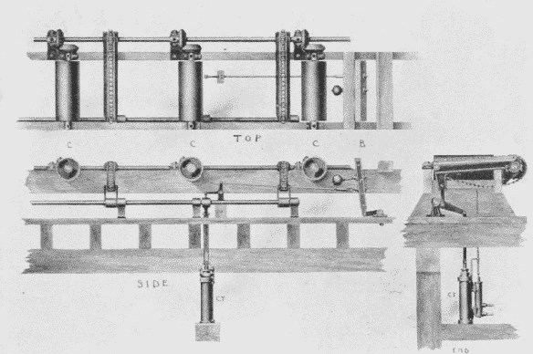
Fig. 44. Automatic Steam Transfer for Timber, Lumber and Slabs. The boards are carried along by the cylinders, CCC, until they hit the bumper, B. This movement admits steam to the cylinder, CY, which raises the revolving chains or skids, which transfers the stock sidewise to other live rollers as required.

Fig. 45. Automatic Gang Lumber-Trimmer. It may be set to cut automatically to any desired length.
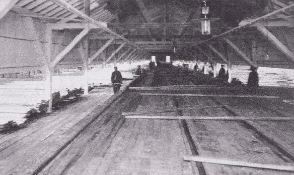
Fig. 46. Lumber Sorting Shed. Virginia, Minnesota.
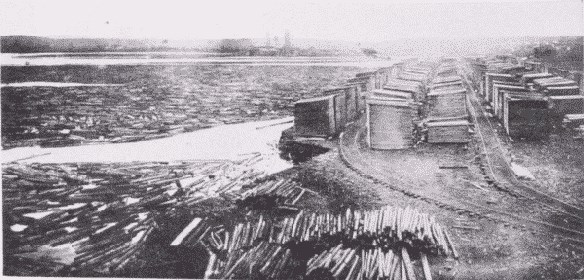
Fig. 47. Wood is carefully and regularly piled in the seasoning-yard.
The boards are now graded as to quality into No. 1, No. 2, etc., Fig. 46, and run out of the mill, to be stacked up in piles, Fig. 47. Big timbers go directly from the saw on the rolls to the back end of the mill, where the first end is trimmed by a butting-saw or cut-off-saw which swings, Fig. 48. The timber is then shoved along on dead rolls and the last end trimmed by the butting-saw to a definite length as specified, and shoved out.
One of the most remarkable features of the modern mill is its speed. From the time the log appears till the last piece of it goes racing out of the mill, hardly more than a minute may have elapsed.
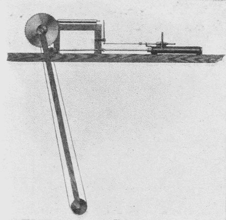
Fig. 48. Cut-off-Saw. This saw trims the ends of timbers.
A large part of the problem of sawmilling is the disposal of the waste. The first of these is the sawdust. In all first class mills, this together with shavings (if a planing-mill is combined) is burned for fuel. It is sucked up from the machines and carried in large tubes to the boiler-room and there is mechanically supplied to the fires. The slabs, once considered as waste, contain much material that is now utilized. From the live rolls, on which all the material falls from the main band-saw, the slabs are carried off by transfer chains, and by another set of five rollers to the "slasher," Fig. 50, which consists of a line of circular-saws placed 4' 1" apart. This slasher cuts up the slabs into lengths suitable for lath or fence-pickets, Fig. 49. Or they can be resawn into 16" lengths for shingles or fire-wood.

