 полная версия
Scientific American Supplement, No. 275, April 9, 1881
The apparatus of M. Baille consists of an annealed silver torsion wire of 2.70 meters long, and a lever 0.50 meter long, carrying at each extremity a ball of copper, gilded, and three centimeters in diameter. Similar balls are fixed at the corners of a square 20.5 meters in the side, and connected in diagonal pairs by fine wire. The lever placed at equal distances from the fixed balls communicates, by the medium of the torsion wire, with the positive pole of a battery, P, the other pole being to earth.
Owing to some unaccountable variations in the change of the lever or needle, M. Baille was obliged to measure the change at each observation. This was done by joining the + pole of the battery to the needle, and one pair of the fixed balls, and observing the deflection; then the deflection produced by the other balls was observed. This operation was repeated several times.
The battery, X, to be measured consisted of ten similar elements, and one pole of it was connected to the fixed balls, while the other pole was connected to the earth. The needle, of course, remained in contact with the + pole of the charging battery, P.
The deflections were read from a clear glass scale, placed at a distance of 3.30 meters from the needle, and the results worked out from Coulomb's static formula,

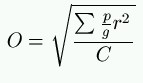
In M. Baillie's experiments, O = 437³, and Σpr²= 32171.6 (centimeter grammes), the needle having been constructed of a geometrical form.
The following numbers represent the potential of an element of the battery–that is to say, the quantity of electricity that the pole of that battery spreads upon a sphere of one centimeter radius. They are expressed in units of electricity, the unit being the quantity of electricity which, acting upon a similar unit at a distance of one centimeter, produces a repulsion equal to one gramme:
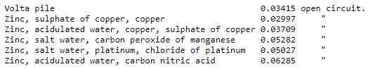
These results were obtained just upon charging the batteries, and are, therefore, slightly higher than the potentials given after the batteries became older. The sulphate of copper cells kept about their maximum value longest, but they showed variations of about 10 per cent.
TELEPHONY BY THERMIC CURRENTS
While in telephonic arrangements, based upon the principle of magnetic induction, a relatively considerable expenditure of force is required in order to set the tightly stretched membrane in vibration, in the so-called carbon telephones only a very feeble impulse is required to produce the differences in the current necessary for the transmission of sounds. In order to produce relatively strong currents, even in case of sound-action of a minimum strength, Franz Kröttlinger, of Vienna, has made an interesting experiment to use thermo electric currents for the transmission of sound to a distance. The apparatus which he has constructed is exceedingly simple. A current of hot air flowing from below upward is deflected more or less from its direction by the human voice. By its action an adjacent thermo-battery is excited, whose current passes through the spiral of an ordinary telephone, which serves as the receiving instrument. As a source of heat the inventor uses a common stearine candle, the flame of which is kept at one and the same level by means of a spring similar to those used in carriage lamps. On one side of the candle is a sheet metal voice funnel fixed upon a support, its mouth being covered with a movable sliding disk, fitted with a suitable number of small apertures. On the other side a similar support holds a funnel-shaped thermo-battery. The single bars of metal forming this battery are very thin, and of such a shape that they may cool as quickly as possible. Both the speaking-funnel and the battery can be made to approach, at will, to the stream of warm air rising up from the flame. The entire apparatus is inclosed in a tin case in such a manner that only the aperture of the voice-funnel and the polar clamps for securing the conducting wires appear on the outside. The inside of the case is suitably stayed to prevent vibration. On speaking into the mouth-piece of the funnel, the sound-waves occasion undulations in the column of hot air which are communicated to the thermo-battery, and in this manner corresponding differences are produced in the currents in the wires leading to the receiving instrument.–Oesterreichische-Ungarische Post.
THE TELECTROSCOPE
This apparatus, which is intended to transmit to a distance through a telegraphic wire pictures taken on the plate of a camera, was invented in the early part of 1877 by M. Senlecq, of Ardres. A description of the first specification submitted by M. Senlecq to M. du Moncel, member of the Paris Academy of Sciences, appeared in all the continental and American scientific journals. Since then the apparatus has everywhere occupied the attention of prominent electricians, who have striven to improve on it. Among these we may mention MM. Ayrton, Perry, Sawyer (of New York), Sargent (of Philadelphia), Brown (of London), Carey (of Boston), Tighe (of Pittsburg), and Graham Bell himself. Some experimenters have used many wires, bound together cable-wise, others one wire only. The result has been, on the one hand, confusion of conductors beyond a certain distance, with the absolute impossibility of obtaining perfect insulation; and, on the other hand, an utter want of synchronism. The unequal and slow sensitiveness of the selenium likewise obstructed the proper working of the apparatus. Now, without a relative simplicity in the arrangement of the conducting wires intended to convey to a distance the electric current with its variations of intensity, without a perfect and rapid synchronism acting concurrently with the luminous impressions, so as to insure the simultaneous action of transmitter and receiver, without, in fine, an increased sensitiveness in the selenium, the idea of the telectroscope could not be realized. M. Senlecq has fortunately surmounted most of these main obstacles, and we give to-day a description of the latest apparatus he has contrived.
TRANSMITTER
A brass plate, A, whereon the rays of light impinge inside a camera, in their various forms and colors, from the external objects placed before the lens, the said plate being coated with selenium on the side intended to face the dark portion of the camera This brass plate has its entire surface perforated with small holes as near to one another as practicable. These holes are filled with selenium, heated, and then cooled very slowly, so as to obtain the maximum sensitiveness. A small brass wire passes through the selenium in each hole, without, however, touching the plate, on to the rectangular and vertical ebonite plate, B, Fig. 1, from under this plate at point, C. Thus, every wire passing through plate, A, has its point of contact above the plate, B, lengthwise. With this view the wires are clustered together when leaving the camera, and thence stretch to their corresponding points of contact on plate, B, along line, C C. The surface of brass, A, is in permanent contact with the positive pole of the battery (selenium). On each side of plate, B, are let in two brass rails, D and E, whereon the slide hereinafter described works.
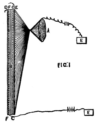
Fig. 1
Rail, E, communicates with the line wire intended to conduct the various light and shade vibrations. Rail, D, is connected with the battery wire. Along F are a number of points of contact corresponding with those along C C. These contacts help to work the apparatus, and to insure the perfect isochronism of the transmitter and receiver. These points of contact, though insulated one from the other on the surface of the plate, are all connected underneath with a wire coming from the positive pole of a special battery. This apparatus requires two batteries, as, in fact, do all autographic telegraphs–one for sending the current through the selenium, and one for working the receiver, etc. The different features of this important plate may, therefore, be summed up thus:
FIGURE 1.
D. Brass rail, grooved and connected with the line wire working the receiver.
F. Contacts connected underneath with a wire permanently connected with battery.
C. Contacts connected to insulated wires from selenium.
E. Brass rail, grooved, etc., like D.
RECEIVER
A small slide, Fig. 2, having at one of its angles a very narrow piece of brass, separated in the middle by an insulating surface, used for setting the apparatus in rapid motion. This small slide has at the points, D D, a small groove fitting into the brass rails of plate, B, Fig. 1, whereby it can keep parallel on the two brass rails, D and E. Its insulator, B, Fig. 2, corresponds to the insulating interval between F and C, Fig. 1.
A, Fig. 3, circular disk, suspended vertically (made of ebonite or other insulating material). This disk is fixed. All round the inside of its circumference are contacts, connected underneath with the corresponding wires of the receiving apparatus. The wires coming from the seleniumized plate correspond symmetrically, one after the other, with the contacts of transmitter. They are connected in the like order with those of disk, A, and with those of receiver, so that the wire bearing the No. 5 from the selenium will correspond identically with like contact No. 5 of receiver.
D, Fig. 4, gutta percha or vulcanite insulating plate, through which pass numerous very fine platinum wires, each corresponding at its point of contact with those on the circular disk, A.
The receptive plate must be smaller than the plate whereon the light impinges. The design being thus reduced will be the more perfect from the dots formed by the passing currents being closer together.
B, zinc or iron or brass plate connected to earth. It comes in contact with chemically prepared paper, C, where the impression is to take place. It contributes to the impression by its contact with the chemically prepared paper.
In E, Fig. 3, at the center of the above described fixed plate is a metallic axis with small handle. On this axis revolves brass wheel, F, Fig. 5.
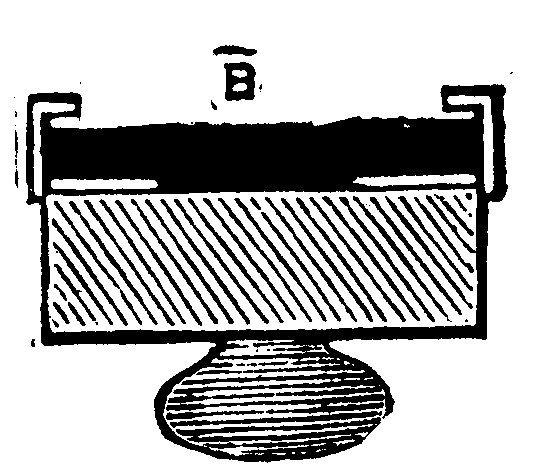
FIG. 2
On handle, E, presses continuously the spring, H, Fig. 3, bringing the current coming from the selenium line. The cogged wheel in Fig. 5 has at a certain point of its circumference the sliding spring, O, Fig. 5, intended to slide as the wheel revolves over the different contacts of disk, A, Fig. 3.
This cogged wheel, Fig. 5, is turned, as in the dial telegraphs, by a rod working in and out under the successive movements of the electro-magnet, H, and of the counter spring. By means of this rod (which must be of a non-metallic material, so as not to divert the motive current), and of an elbow lever, this alternating movement is transmitted to a catch, G, which works up and down between the cogs, and answers the same purpose as the ordinary clock anchor.
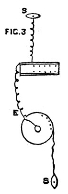
FIG. 3
This cogged wheel is worked by clockwork inclosed between two disks, and would rotate continuously were it not for the catch, G, working in and out of the cogs. Through this catch, G, the wheel is dependent on the movement of electro-magnet. This cogged wheel is a double one, consisting of two wheels coupled together, exactly similar one with the other, and so fixed that the cogs of the one correspond with the void between the cogs of the others. As the catch, G, moves down it frees a cog in first wheel, and both wheels begin to turn, but the second wheel is immediately checked by catch, G, and the movement ceases. A catch again works the two wheels, turn half a cog, and so on. Each wheel contains as many cogs as there are contacts on transmitter disk, consequently as many as on circular disk, A, Fig. 3, and on brass disk within camera.
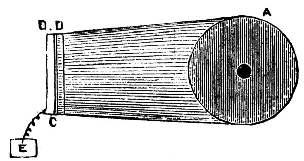
FIG. 4
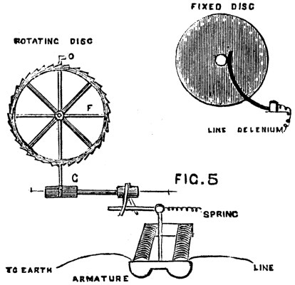
FIG. 5
Having now described the several parts of the apparatus, let us see how it works. All the contacts correspond one with the other, both on the side of selenium current and that of the motive current. Let us suppose that the slide of transmitter is on contact No. 10 for instance; the selenium current starting from No. 10 reaches contact 10 of rectangular transmitter, half the slide bearing on this point, as also on the parallel rail, communicates the current to said rail, thence to line, from the line to axis of cogged wheel, from axis to contact 10 of circular fixed disk, and thence to contact 10 of receiver. At each selenium contact of the rectangular disk there is a corresponding contact to the battery and electro-magnet. Now, on reaching contact 10 the intermission of the current has turned the wheel 10 cogs, and so brought the small contact, O, Fig. 5, on No. 10 of the fixed circular disk.
As may be seen, the synchronism of the apparatus could not be obtained in a more simple and complete mode–the rectangular transmitter being placed vertically, and the slide being of a certain weight to its fall from the first point of contact sufficient to carry it rapidly over the whole length of this transmitter.
The picture is, therefore, reproduced almost instantaneously; indeed, by using platinum wires on the receiver connected with the negative pole, by the incandescence of these wires according to the different degrees of electricity we can obtain a picture, of a fugitive kind, it is true, but yet so vivid that the impression on the retina does not fade during the relatively very brief space of time the slide occupies in traveling over all the contacts. A Ruhmkorff coil may also be employed for obtaining sparks in proportion to the current emitted. The apparatus is regulated in precisely the same way as dial telegraphs, starting always from first contact. The slide should, therefore, never be removed from the rectangular disk, whereon it is held by the grooves in the brass rails, into which it fits with but slight friction, without communicating any current to the line wires when not placed on points of contact.
[Continued from SUPPLEMENT No. 274, page 4368.]
THE VARIOUS MODES OF TRANSMITTING POWER TO A DISTANCE.2
But allowing that the figure of 22 H. P., assumed for this power (the result in calculating the work with compressed air being 19 H. P.) may be somewhat incorrect, it is unlikely that this error can be so large that its correction could reduce the efficiency below 80 per cent. Messrs. Sautter and Lemonnier, who construct a number of compressors, on being consulted by the author, have written to say that they always confined themselves in estimating the power stored in the compressed air, and had never measured the gross power expended. Compressed air in passing along the pipe, assumed to be horizontal, which conveys it from the place of production to the place where it is to be used, experiences by friction a diminution of pressure, which represents a reduction in the mechanical power stored up, and consequently a loss of efficiency.
The loss of pressure in question can only be calculated conveniently on the hypothesis that it is very small, and the general formula,
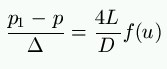
D'Aubuisson gives for this case, in his Traité d'Hydraulique, a rather complicated formula, containing a constant deduced from experiment, whose value, according to a calculation made by the author, is approximately b1 = 0.0003. This constant was determined by taking the mean of experiments made with tin tubes of 0.0235 meter (15/16 in.), 0.05 meter (2 in.), and 0.10 meter (4 in.) diameter; and it was erroneously assumed that it was correct for all diameters and all substances.
M. Arson, engineer to the Paris Gas Company, published in 1867, in the Mémoires de la Société des Ingénieurs Civils de France, the results of some experiments on the loss of pressure in gas when passing through pipes. He employed cast-iron pipes of the ordinary type. He has represented the results of his experiments by the binomial formula, au + bu², and gives values for the coefficients a and b, which diminish with an increase in diameter, but would indicate greater losses of pressure than D'Aubuisson's formula. M. Deviller, in his Rapport sur les travaux de percement du tunnel sous les Alpes, states that the losses of pressure observed in the air pipe at the Mont Cenis Tunnel confirm the correctness of D'Aubuisson's formula; but his reasoning applies to too complicated a formula to be absolutely convincing.
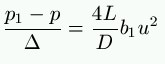
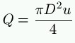
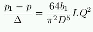
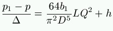
Quite recently M. E. Stockalper, engineer-in-chief at the northern end of the St. Gothard Tunnel, has made some experiments on the air conduit of this tunnel, the results of which he has kindly furnished to the author. These lead to values for the coefficient b1 appreciably less than that which is contained implicitly in D'Aubuisson's formula. As he experimented on a rising pipe, it is necessary to introduce into the formula the difference of level, h, between the two ends; it then becomes
The divergence from the results obtained by M. Arson's formula does not arise from a difference in size, as this is taken into account. The author considers that it may be attributed to the fact that the pipes for the St. Gothard Tunnel were cast with much greater care than ordinary pipes, which rendered their surface smoother, and also to the fact that flanged joints produce much less irregularity in the internal surface than the ordinary spigot and faucet joints.
Lastly, the difference in the methods of observation and the errors which belong to them, must be taken into account. M. Stockalper, who experimented on great pressures, used metallic gauges, which are instruments on whose sensibility and correctness complete reliance cannot be placed; and moreover the standard manometer with which they were compared was one of the same kind. The author is not of opinion that the divergence is owing to the fact that M. Stockalper made his observations on an air conduit, where the pressure was much higher than in gas pipes. Indeed, it may be assumed that gases and liquids act in the same manner; and, as will be [1] explained later on, there is reason to believe that with the latter a rise of pressure increases the losses of pressure instead of diminishing them.