 полная версия
Scientific American, Volume 40, No. 13, March 29, 1879
There had been no lack of copying telegraphs hitherto. We have Bakewell's, Casselli's, Meyer's, and D'Arlincourt's, so recently tried at our General Post Office by Mr. Preece. All of these instruments telegraph an almost perfect copy of the writing or sketch submitted to them by means of synchronous mechanism. But the process is necessarily complex and slow; whereas by the new device a person may take the writing pencil in his hand, and himself transmit his message in the act of writing it.
The principle which guided Mr. Cowper to a solution of the problem which he has successfully overcome, is the well known mathematical fact that the position of any point in a curve can be determined by its distance from two rectangular co-ordinates. It follows, then, that every position of the point of a pencil, stylus, or pen, as it forms a letter, can be determined by its distance from two fixed lines, say the adjacent edges of the paper. Moreover it is obvious that if these distances could be transmitted by telegraph and recombined so as to give a resultant motion to a duplicate pen, a duplicate copy of the original writing would be produced. But inasmuch as the writing stylus moves continuously over the paper, the process of transmission would require to be a continuous one; that is to say, the current traversing the telegraph line, and conveying the distances in question (or what comes to the same thing, the up and down, and direct sidelong ranges of the stylus) would require to vary continuously in accordance with the range to be transmitted.
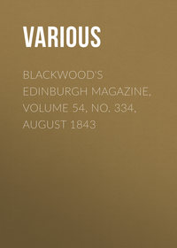
Mr. Cowper effects this by employing two separate telegraphic circuits, each with its own wire, battery, sending, and receiving apparatus. One of these circuits is made to transmit the up and down component writing of the pencil's motion, while the other simultaneously transmits its sidelong component. At the receiving station these two components are then recomposed by a pantograph arrangement of taut cords, or levers, and the resultant motion is communicated to the duplicate pen at that place. The plan adopted by Mr. Cowper to transmit each continuously varying component is to cause the resistance of the circuit to vary very closely with the component in question. Fig. 5 shows how the apparatus is theoretically arranged for this purpose. P is the writing style, which is held in the writer's hand in the ordinary way, while he shapes the letters one by one on paper pulled uniformly underneath by means of clockwork. To P are attached, at right angles, two arms, a a, one for each circuit; but as it is only necessary to consider one of the circuits, say that sending up and down motions, we will confine our attention for the present to the arm, a. One pole of the sending battery, B, is connected to the arm, a, the other pole being connected to earth. Now the arm, a, is fitted with a sliding contact at its free extremity, and as the pencil, P, is moved in writing, a slides lengthwise across the edges of a series of thin metal contact plates, C, insulated from each other by paraffined paper. Between each pair of these plates there is a resistance coil, C, and the last of these is connected through the last plate to the line, L. It will be seen that as a slides outward across the plates the current from the battery has to pass through fewer coils, since a short-circuits a number of coils proportional to its motion. But the fewer of these coils in circuit the stronger will be the current in the line; so that the extent of the motion of the arm, a, in the direction of its length, that is to say, the direct component of the motion of the pencil along the line of the arm, a, is attended by a corresponding change in the current traversing the line. If the pencil makes a long up and down stroke there will be a strong current in the line, if a short one there will be a weak current, and so on. A precisely similar arrangement is used to transmit the sidelong motion of the pencil along the line, L.
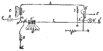
Fig. 5.
The current from the line, L, flows at the receiving station through a powerful galvanometer, G, to earth. The galvanometer has a stout needle, one tip of which is connected to a duplicate pen, P, by a thread, t, which is kept taut by a second thread stretched by a spring, s'. The current from the line, L', flows through a similar galvanometer, G', to earth. The needle of G' is also connected to the pen, P, by a taut thread, t', stretched by means of the spring, s. Now, since the needle of each of these galvanometers deflects in proportion to the strength of the current flowing through its coil, the points of these two needles keep moving with the varying currents. But since these currents vary the motions of the sending pen, the receiving pen controlled by the united movements of the needles will trace out a close copy of the original writing. We give on another page a facsimile of a sentence written by Mr. Cowper's telegraph.
THE COWPER WRITING TELEGRAPH.
The receiving pen is a fine glass siphon, drawing off aniline ink from a small glass holder. There are thirty-two coils, C, in each circuit, with a corresponding number of contact plates, c, so as to get accuracy of working. A few Daniell's cells are sufficient to operate the apparatus, and writing has been already sent successfully over a line 40 miles in length. The writing may be received either of the same size or larger or smaller than the original, as the case may be. At present the writing must not be too hurried, that is, unless the characters are bold and well formed; but further improvement will, of course, quicken the working of the apparatus.
The engravings, Figs. 1 to 4, illustrate the actual apparatus. Fig. 4 is a plan of the sending instrument, with the writing pencil, a, the traveling paper, b, the light connecting rods or arms, d (which correspond to a in the theoretical diagram above), the series of metal contact plates over which these arms slide, the resistance coils connected to these plates, and the battery and line wires. It will be seen that each arm, d, is connected to its particular battery, and each set of contact plates to its particular line. Fig. 3 is an elevation of the sending instrument, in which a is the pencil as before, c c the contact plates over which the arms, d d, slide, f f the coils, and b the traveling slip of paper.
Fig. 2 is a plan of the receiving instrument, in which h h are the light pivoted needles surrounded by coils of fine insulated copper wires, i i, and controlled in their zero position by the electro-magnets, j j j j, placed underneath, the whole forming a pair of galvanoscopes or current detecters, one for each line. It will be understood that the varying currents from the lines are allowed to flow through the coils, i i, so as to deflect the needles, and that the deflections of the needles follow, so to speak, the variations of the currents. The electro-magnets are magnetized by a local battery; permanent magnets might, however, take their place with a gain in simplicity.
Now the writing pen, k, is connected to the nearest tip of the needle, h, of each galvanoscope by threads, n n, which are kept taut by the fibers, o1 o2 o3, the springs, o, and the pins, o4. In this way the motions of the needles are recombined in the motion of the duplicate pen upon the paper, p.
Fig. 1 is an elevation of the receiving instrument, in which i i are the coils as before, j j j j the controlling electro-magnets, k is the writing siphon dipping with its short leg into the ink well, m, and l is the bridge from which the writing siphon is suspended by means of a thread and spring. The long leg of the siphon reaches down to the surface of the paper, p, which is pulled along beneath it in contact with the film of ink filling the point of the tube. When the siphon is at rest its point marks a zero line along the middle of the paper, but when the receiver is working, the siphon point forms each letter of the message upon the paper as it passes.—Engineering.
ALUMINUM
The splendid exhibit of the French aluminum manufacturers at the late Exhibition has again called attention to that metal, which is so admirably adapted to many purposes on account of its great lightness and its stability under the influence of the atmosphere. While aluminum industry has heretofore been thought to be confined to France solely, we are now told by Mr. C. Bambery, in the Annual Report of the Society of Berlin Instrument Makers, that for some years past aluminum has been extensively manufactured in Berlin.
Three firms especially (Stückradt, Häcke, and Schultze) are engaged in this branch of industry.
The articles manufactured principally are nautical instruments, as sextants, compasses, etc. The German navy is supplied throughout with aluminum instruments. As a proof of the superiority of German aluminum, it may here be mentioned that the normal sets of weights and balances used by the International Commission for the regulation of weights and measures, which lately was in session at Paris, were obtained from Stückradt, in Berlin, and not from any of the firms at Paris, the reputed seat of aluminum industry.
Aluminum is, in Berlin, generally used pure, and cast pieces only are composed of aluminum containing about 5 per cent of silver.
Nevertheless the use of aluminum will remain limited, even in case the cost of manufacturing it could be materially reduced, until some method shall have been discovered by which aluminum may be soldered.
This difficulty has, in spite of all efforts, not yet been overcome, and for some purposes, to which the metal would otherwise be well adapted, it remains so far unavailable. Here then is a chance for some ingenious mind.
AN IMPROVED DOOR BOLT
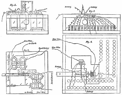
The accompanying engraving represents, in perspective and in section, an improved door bolt, recently patented by Mr. Thomas Hoesly, of New Glaras, Wis.
HOESLY'S DOOR BOLT.
The principal features of this bolt will be understood by reference to the engraving. On the plate or body are cast two loops or guides for the bolt, and the plate is slotted under the bolt, and a lug projects into the slot and bears against a spring contained by a small casing riveted to the back of the plate. The end of the bolt is beveled, and its operation is similar to that of the ordinary door latch. Two handles are provided, one of which is of sufficient length to reach through the door, and a pawl or dog accompanies the bolt, which may be attached to the door with a single screw, and is to be used in locking the door. The bolt is very simple and strong, suitable for shops, out-buildings such as barns, stables, etc., and some of the doors of dwellings.
Further information may be obtained by addressing the inventor, as above.
Chimney Flues
Messrs. W. H. Jackson & Co., of this city, whose long experience in treating refractory flues gives weight to their opinion, communicate to the American Architect the following useful information:
To secure a good draught the chimney should be of sufficient size, should be carried up above surrounding objects, should be as straight as possible throughout its length, and should be as smooth as possible inside, to avoid friction. As a draught is caused by unequal temperatures, the chimney should be so arranged as to avoid a rapid radiation of heat. If in an exterior wall there should be at least 8 inches of brickwork between the flue and the exterior surface. For country houses it is much better to have the chimneys run up through the interior, as the flue is more easily kept warm, and the heat that is radiated helps to warm the house. The most frequent cause of a "smoky chimney" is the insufficient size of the flue for the grate or fireplace connected therewith. The flue should not be less than one eighth the capacity of the square of the width and height of the grate or fireplace. That is, if the grate has a front opening 20 inches wide and 26 inches high, the flue should be 8 in. x 8 in.; or, with an opening 36 inches wide and 32 inches high, the flue should be 12 in. x 12 in.; and, to get the best result, the opening into the flue from the grate or fireplace should be of a less number of square inches than the square of the flue, and never larger, as no more air should be admitted at the inlet than can be carried through the flue. Where there is more than one inlet to the same flue, the sum of all the inlets should not more than equal the size of the flue. A number of stoves may be connected with the same flue, one above another, if this rule is observed.
A square flue is better than a narrow one, as in two flues containing the same number of square inches the square flue would have the smallest amount of wall surface, and consequently less friction for the ascending currents, and less absorption of heat by the walls. Chimneys should be closely built, having no cracks nor openings through which external air may be drawn to weaken the draught. If they could be made throughout their length as impervious to air as a tube of glass, with interior surface as smooth, one cause of smoky chimneys would be removed. A downward current of air is frequently caused by some contiguous object higher than the chimney, against which the wind strikes. This higher object may sometimes be quite a distance from the chimney, and still affect it badly. A good chimney top constructed to prevent a down draught will remedy this difficulty. Each grate or fireplace should have a flue to itself. Under very favorable conditions, two grates or fireplaces might be connected with the same flue, but it is not a good plan. We have known grates and fireplaces connected with two flues, where they have been built under a window for instance, and, owing to there being insufficient room for a flue of suitable size, a flue has been run up on each side of the window. This is a very bad plan, and never can work well; it requires too much heat to warm both flues, and if the room in which the grate or fireplace is situated should be pretty close, so that there was no other entrance for air, there is danger that it would circulate down one flue and up the other, forcing smoke out of the fireplace into the room.
IMPROVED FURNACE FOR BURNING GARBAGE
The refuse matter and garbage of large cities is in the main composed of animal and vegetable offal of the kitchens; of the sweepings of warehouses, manufactories, saloons, groceries, public and private houses; of straw, sawdust, old bedding, tobacco stems, ashes, old boots, shoes, tin cans, bottles, rags, and feathers; dead cats, dogs, and other small animals; of the dust and sweepings of the streets, the condemned fruit, vegetables, meat, and fish of the markets, all of which compose a mass of the most obnoxious and unhealthy matter that can be deposited near human habitations.
The inventor of the furnace shown in the accompanying engravings aims to produce a change of form and of chemical nature and a great reduction in bulk of all such refuse and garbage within the limits of the city where it accumulates, without screening, separating, preparing, or mixing, without the expense of using other fuel, without any offensive odors being generated in the operation, and to produce an entirely unobjectionable residuum or product that may be made useful.
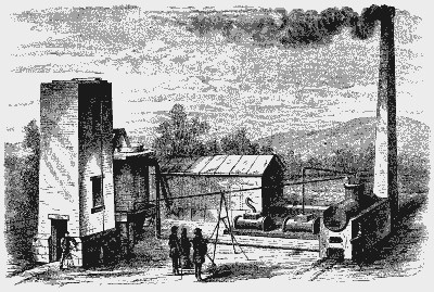
Fig. 1.—FOOTE'S FURNACE FOR BURNING GARBAGE.
As a rule organic matter largely preponderates in the refuse, being as high in some instances as 94 per cent. There is always more than enough to generate sufficient heat to fuse the earthy or inorganic portion, which is mainly composed of sand, clay, and the alkalies from the coal and vegetable ashes, etc.
By producing a high degree of heat in the combustion of the organic portion of the refuse with a forced blast or forced draught, the non-combustible elements are fused, and form a vitreous slag, which is entirely inodorous and unobjectionable, and which may be utilized for many purposes.
The upper section or cone of the consuming furnace is built of boiler iron, and lined with fire brick resting upon an iron plate, which is supported by iron columns.
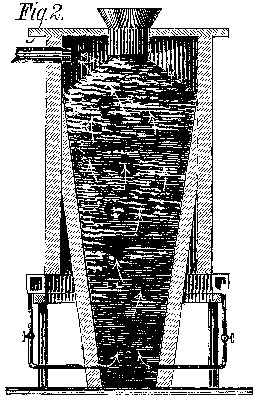
The hearth is made of fire brick, and is in the form of an inverted cone, being smaller at the bottom and larger at the top, as shown in Fig. 2.
The sides of the hearth are perforated near the bottom with arches for the tuyeres or blast pipes, and also in front for the special blast pipe and the tapping hole. The top of the furnace is closed with an iron plate, provided with a circular opening, through which the hopper enters the top of the furnace.
At the left in the larger engraving is seen an elevator, operated by a steam engine, for conveying the garbage and refuse to a platform, whence it is projected into the furnace by an inclined plane or chute.
Gas or smoke conductors convey the gas from the top of the furnace to the furnace of the boiler and to the heating oven, where it is used in heating air, which is conveyed through the iron pipes passing through the heating oven into a wind box, from which it enters the furnace at several points near the bottom by means of the tuyere pipes.
SECTION OF FURNACE.
The consumption of the garbage is effected near the bottom of the furnace, where the air is forced in, and is continued as long as the blast is applied, and while burning at the base it is continually sinking down at the top, so that it is necessary to keep filling all the time. The odoriferous gases and the hot products of such combustion are forced upward through the superimposed mass, and escape to the fires of the boiler and heating oven, and, being largely composed of carbonic oxide and the hydrocarbon gases distilled from the animal and vegetable offal of the garbage, are thoroughly consumed; and it is said that by this means not only are all the offensive odors destroyed, but the heat generated is utilized for making steam and heating the air used for blast.
The refuse in its descent through the high furnace is exposed to the drying action of the hot gases of distillation and the hot products of combustion, its temperature increasing in its descent the nearer it approaches the tuyeres, and becomes completely desiccated and combustible when it reaches the blast. The high heat in this way obtained by the combustion of the organic portion melts all of the inorganic portion, forming a vitreous slag or glass, which may be allowed to run continuously, or by closing the tap may be allowed to accumulate, and can be drawn off at intervals. If there is an adequate supply of clay and sand in the refuse to combine with the ashes, the slag will run hot and free. The combination of silex or alumina and an alkali in proper portions always yields a fusible, easy-running compound.
The molten slag, as it runs from the furnace, may be discharged into tanks of cold water, which will pulverize or granulate it, making it like fine sand, or as it pours over a runner, through which it flows, if struck with a forcible air or steam blast it will be spun into fine thread-like wool.
The furnace once lighted and started may be kept running day and night continuously for days, months, or years, if desired; but if it becomes necessary to stop at any time, the tuyere pipes may be removed and the holes all stopped with clay, so as to entirely shut off the supply of air, and it will then hold in fire for many days, and will be in readiness to start again at any time the pipes are replaced and the blast turned on.
This furnace is the invention of Mr. Henry R. Foote, of Stamford, Conn.
AN ANCIENT GREEK VASE
The vase shown in the accompanying engravings must not be classed with ordinary ceramic ware, as it is a veritable work of art. It is the celebrated cup of Arcesilaus, which is preserved in the collection of the library of Richelieu street after having figured in the Durand Museum. It was found at Vulsei, in Etruria. It was made by a potter of Cyrene, the capital of Cyrenaica, founded by Greeks from the island of Thera. It is remarkable that Cyrene, removed from the center of Grecian manufacture, should possess a manufactory of painted vases from which have come so many works of art. The traveler, Paul Lucas, discovered in the necropolis of Cyrene, in 1714, many antique vases, both in the tombs and in the soil. One of them is still preserved in the Museum at Leyden. The Arcesilaus, who is represented on this vase, is not the celebrated skeptical philosopher of that name; it is Arcesilaus, King of Cyrenaica, who was sung by Pindar, and who was vanquished in the Pythian games under the 80th Olympiad (458 years B.C.).
The height of this vase is 25 centimeters, its diameter 28 centimeters. The paste is very fine, of a pale red. It is entirely coated with a black groundwork, which has been generally re-covered with a yellowish white clay, baked on.
According to M. Brongniart, this piece has been subjected to the baking process at least two or three times, thus indicating that the ceramic art had made considerable progress in Cyrene even at that remote epoch.
The following description of this vase is given in the catalogue of the Durand Museum: The King Arcesilaus is seated under a pavilion upon the deck of a ship. His head is covered with a kind of hat with a large brim, and his hair hangs down upon his shoulders. He is clothed in a white tunic and embroidered cloak or mantle, and he carries a scepter in his left hand; under his seat is a leopard, and his right hand he holds toward a young man, who makes the same gesture, and he is weighing in a large scale assafœtida, which is being let down into the hold of the ship. We know that he deals with assafœtida because one of the personages (the one who lifts up his arm toward the beam of the scale) holds in his right hand something resembling that which is in the scale, and the Greek word traced near it signifies "that which prepares silphium." Assafœtida, the resinous matter of the silphium, is used largely by the Greeks in the preparation of their food. The Orientals to-day make frequent use of it and call it the delight of the gods; while in Europe, because of its repulsive odor, it has long been designated as stircus diaboli.
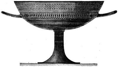
Fig. 1.—ANCIENT GREEK VASE.
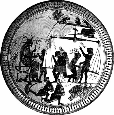
Fig. 2.—TOP OF GREEK VASE.
Snow-Raised Bread
Somebody thinks he has discovered that snow, when incorporated with dough, performs the same office as baking powder or yeast. "I have this morning for breakfast," says a writer in the English Mechanic, "partaken of a snow-raised bread cake, made last evening as follows: The cake when baked weighed about three quarters of a pound. A large tablespoonful of fine, dry, clean snow was intimately stirred with a spoon into the dry flour, and to this was added a tablespoonful of caraways and a little butter and salt. Then sufficient cold water was added to make the dough of the proper usual consistence (simply stirred with the spoon, not kneaded by the warm hands), and it was immediately put into a quick oven and baked three quarters of an hour. It turned out both light and palatable. The reason," adds the writer, "appears to be this: the light mass of interlaced snow crystals hold imprisoned a large quantity of condensed atmospheric air, which, when the snow is warmed by thawing very rapidly in the dough, expands enormously and acts the part of the carbonic acid gas in either baking powder or yeast. I take the precise action to be, then, not due in any way to the snow itself, but simply to the expansion of the fixed air lodged between the interstices of the snow crystals by application of heat. This theory, if carefully followed out, may perchance give a clew to a simple and perfectly innocuous method of raising bread and pastry." And stop the discussion as to whether alum in baking powders is deleterious to health or otherwise.